Upgrade to Pro — share decks privately, control downloads, hide ads and more …

Controller Design for Symbolic Input-Output Sys...

konakalab
August 27, 2026

Controller Design for Symbolic Input-Output Systems Using Feedforward Neural Networks

This was presented at 23rd IFAC World Congress (https://www.ifac2026.org/fairDash.do). Movies are not included due to the specifications of speakerdeck.

konakalab

August 27, 2026

Transcript

26 slides
  1. Controller Design for Symbolic Input-Output Systems Using Feedforward Neural Networks

    Kohtaroh HIBINO∗, Eiji KONAKA (Meijo University, Japan)
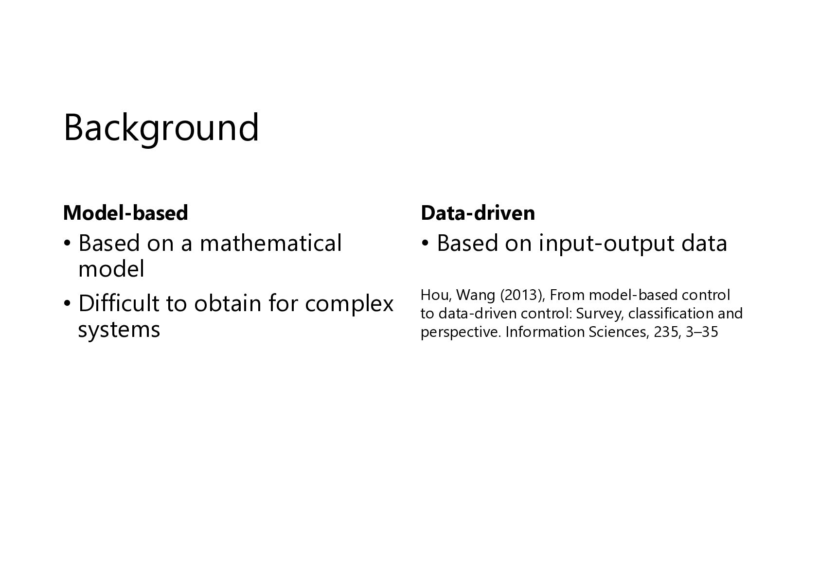
  2. Background Model-based Data-driven • Based on a mathematical model •

    Difficult to obtain for complex systems • Based on input-output data Hou, Wang (2013), From model-based control to data-driven control: Survey, classification and perspective. Information Sciences, 235, 3–35
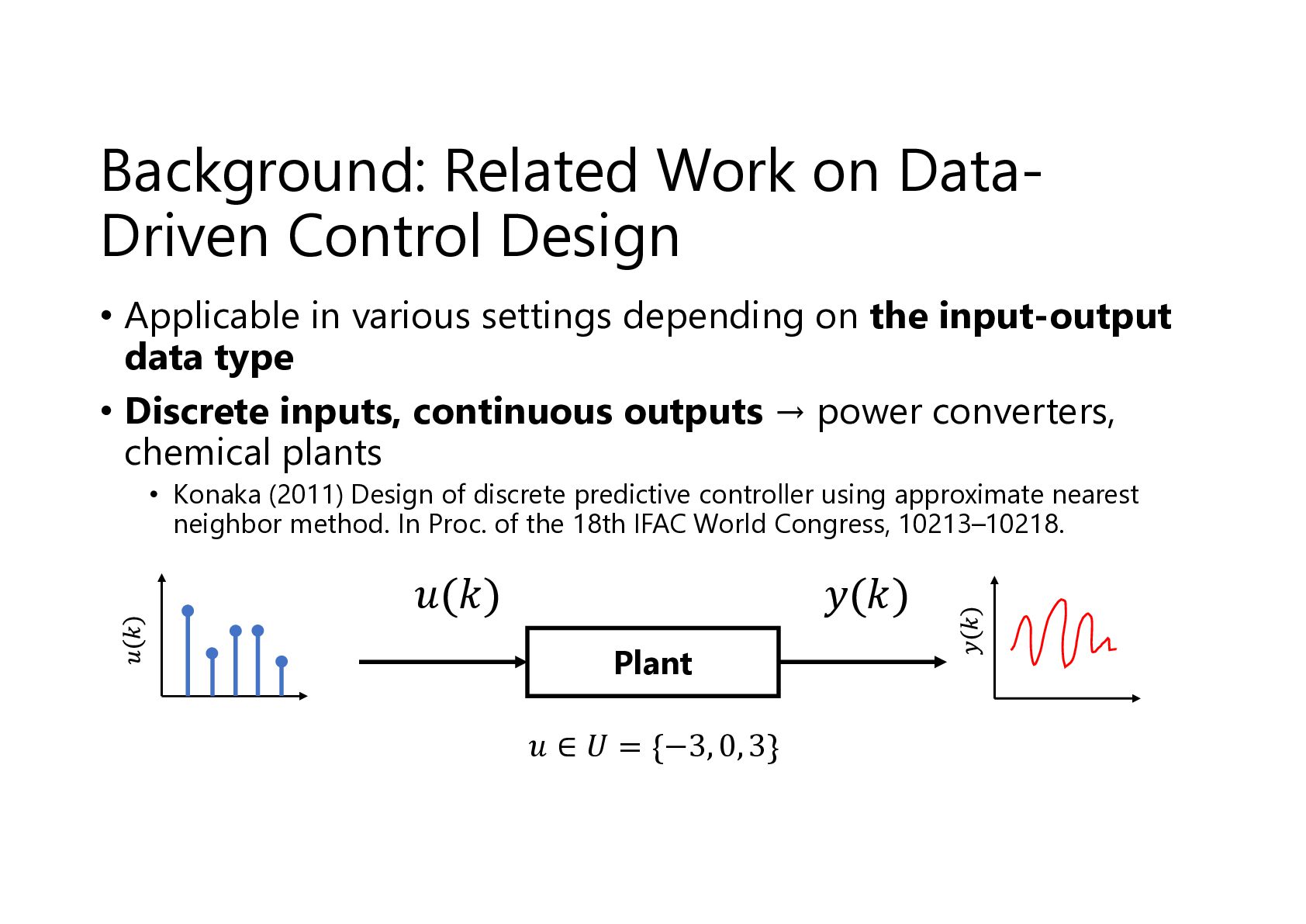
  3. Background: Related Work on DataDriven Control Design • Applicable in

    various settings depending on the input-output data type • Discrete inputs, continuous outputs → power converters, chemical plants • Konaka (2011) Design of discrete predictive controller using approximate nearest neighbor method. In Proc. of the 18th IFAC World Congress, 10213–10218. 𝑢(𝑘) 𝑦(𝑘) Plant 𝑢 ∈ 𝑈 = {−3, 0, 3}
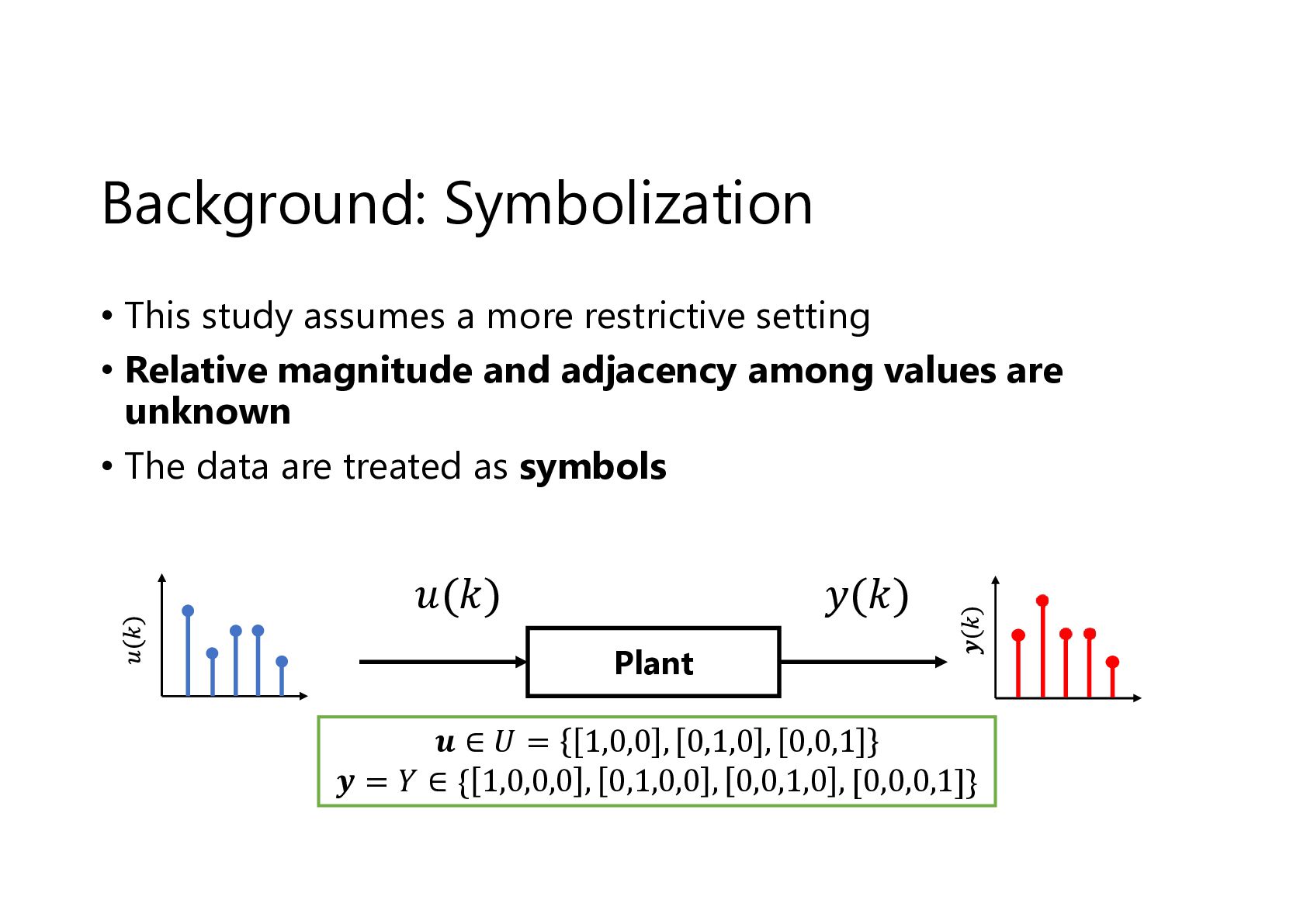
  4. Background: Symbolization • This study assumes a more restrictive setting

    • Relative magnitude and adjacency among values are unknown • The data are treated as symbols 𝑢(𝑘) 𝑦(𝑘) Plant 𝒖 ∈ 𝑈 = 1,0,0 , 0,1,0 , 0,0,1 𝒚 = 𝑌 ∈ { 1,0,0,0 , 0,1,0,0 , 0,0,1,0 , [0,0,0,1]}
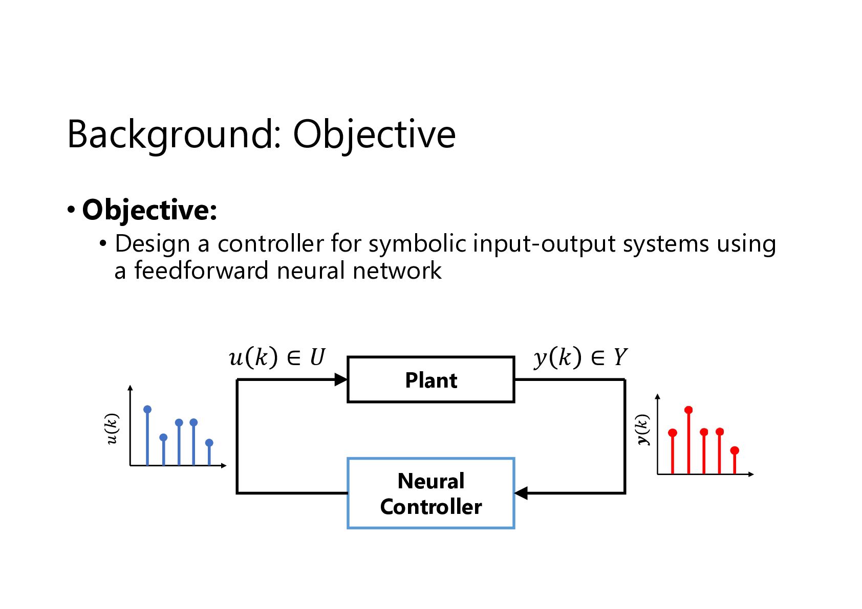
  5. Background: Objective • Objective: • Design a controller for symbolic

    input-output systems using a feedforward neural network 𝑢 𝑘 ∈𝑈 Plant Neural Controller 𝑦 𝑘 ∈𝑌
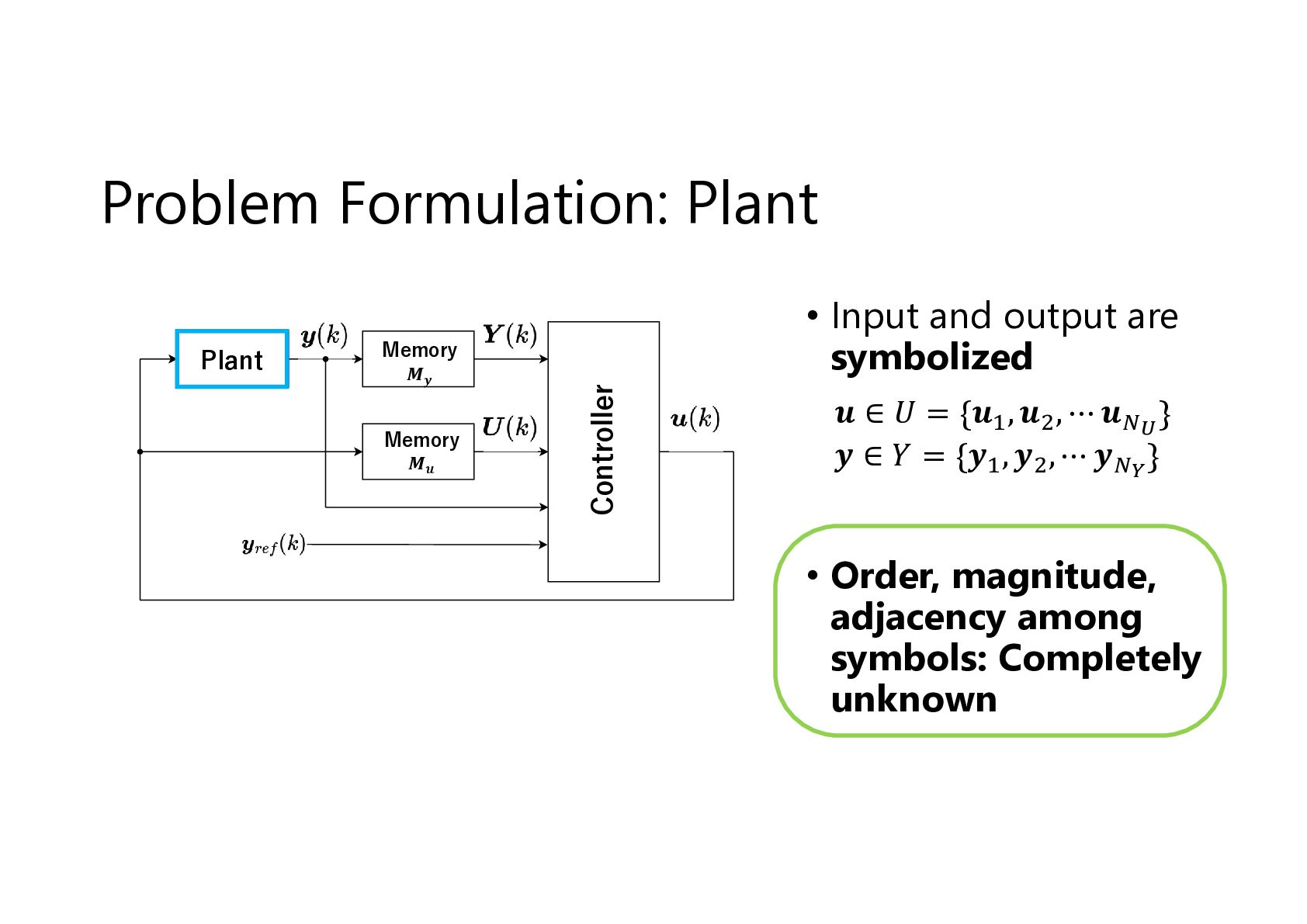
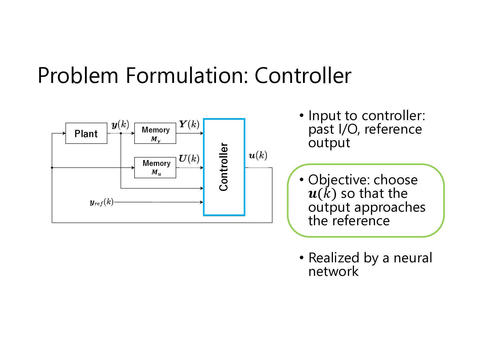
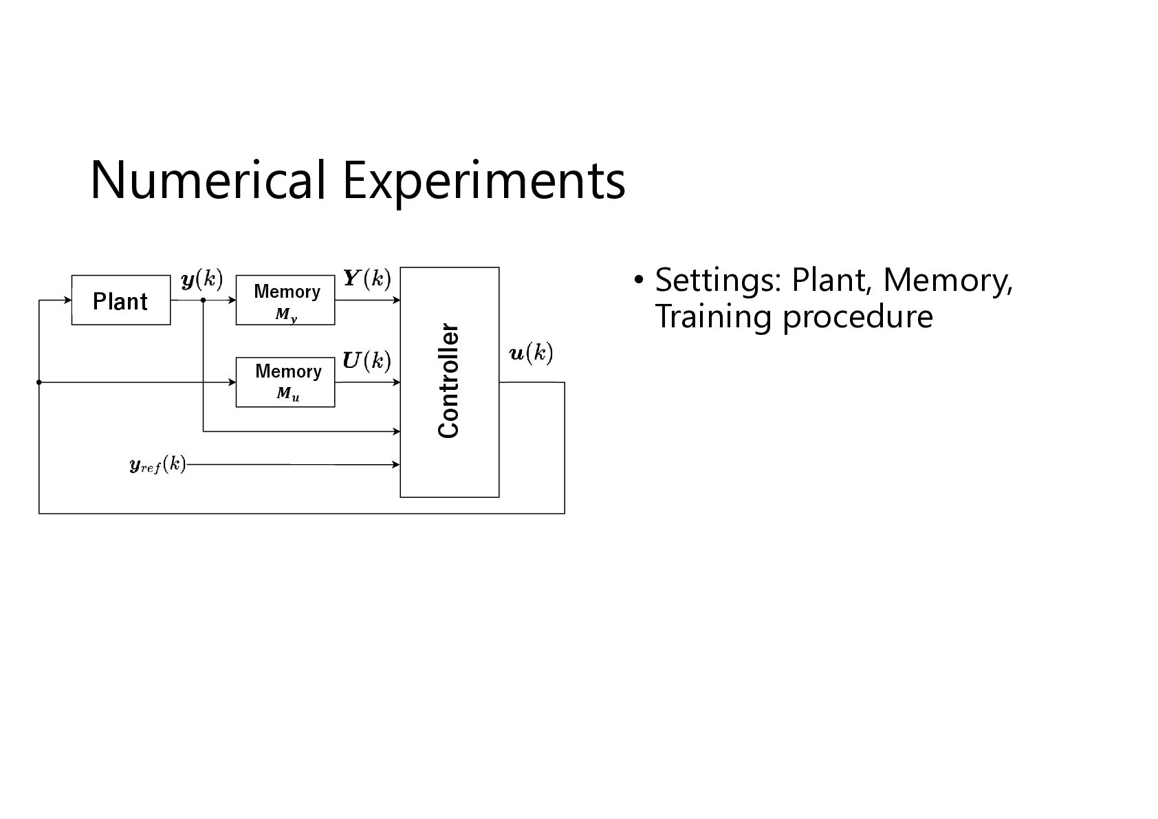
  6. Problem Formulation: Plant Memory 𝑴𝒚 Memory 𝑴𝒖 Controller Plant •

    Input and output are symbolized 𝒖 ∈ 𝑈 = {𝒖 , 𝒖 , ⋯ 𝒖 } 𝒚 ∈ 𝑌 = {𝒚 , 𝒚 , ⋯ 𝒚 } • Order, magnitude, adjacency among symbols: Completely unknown
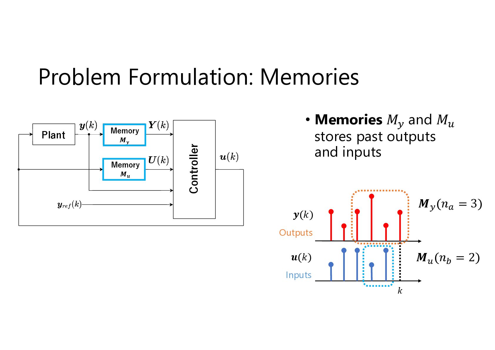
  7. Plant Memory 𝑴𝒚 Memory 𝑴𝒖 Controller Problem Formulation: Memories •

    Memories 𝑀 and 𝑀 stores past outputs and inputs 𝑴 (𝑛 = 3) 𝒚(𝑘) Outputs 𝑴 (𝑛 = 2) 𝒖(𝑘) Inputs 𝑘
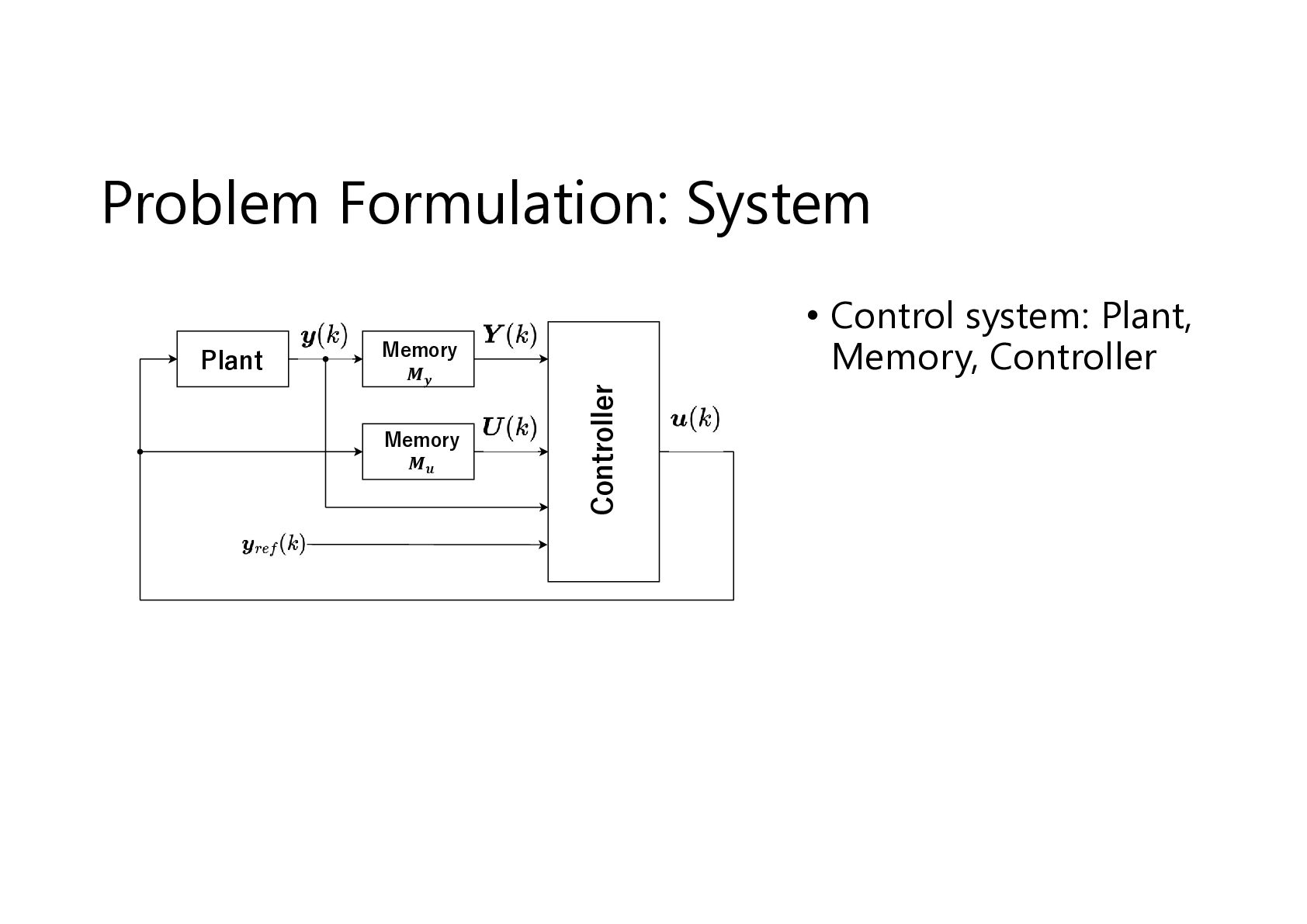
  8. Plant Memory 𝑴𝒚 Memory 𝑴𝒖 Controller Problem Formulation: Controller •

    Input to controller: past I/O, reference output • Objective: choose 𝒖(𝑘) so that the output approaches the reference • Realized by a neural network
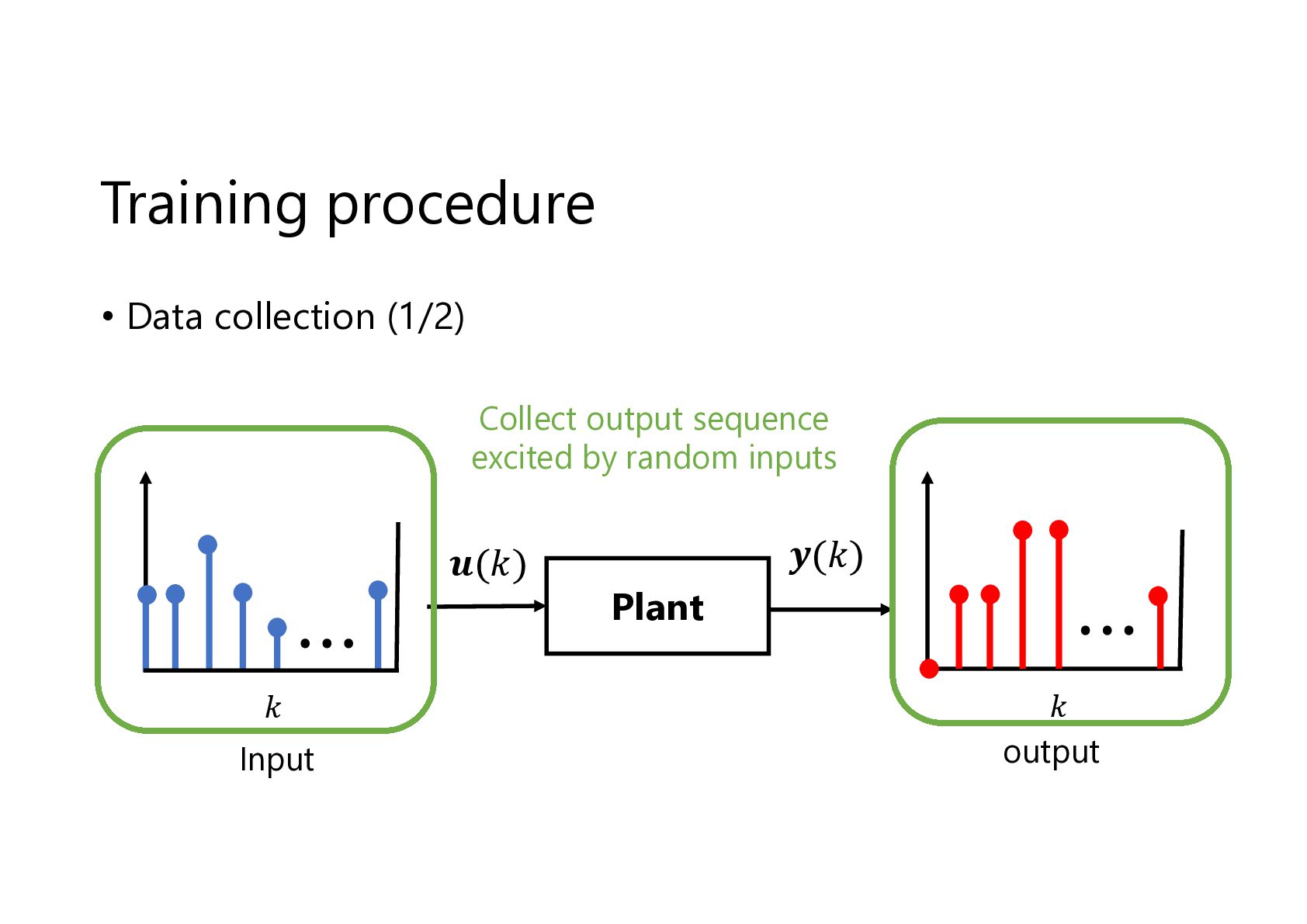
  9. Training procedure • Data collection (1/2) Collect output sequence excited

    by random inputs 𝒖(𝑘) 𝑘 Input 𝒚(𝑘) Plant 𝑘 output
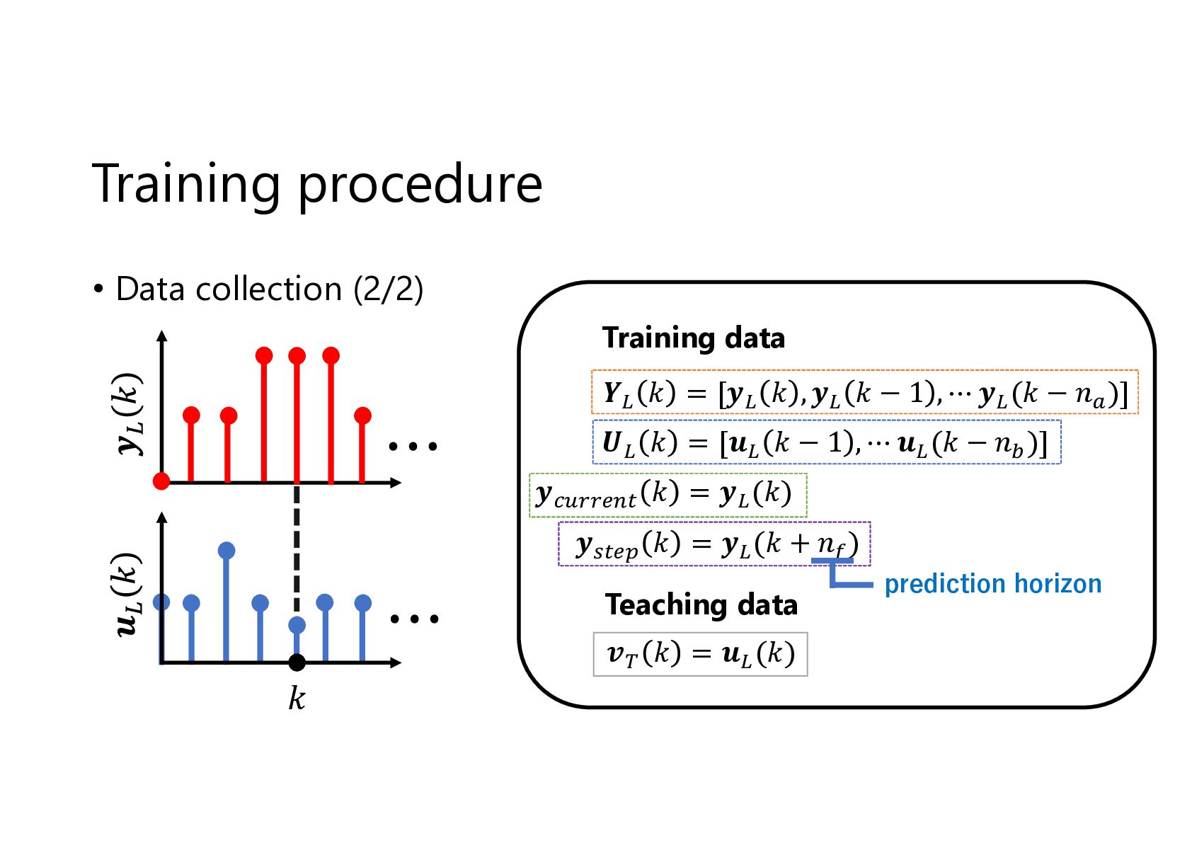
  10. Training procedure • Data collection (2/2) Training data 𝒀 𝑘

    = [𝒚 𝑘 , 𝒚 𝑘 − 1 , ⋯ 𝒚 (𝑘 − 𝑛 )] 𝑼 𝑘 = [𝒖 𝑘 − 1 , ⋯ 𝒖 (𝑘 − 𝑛 )] 𝒚 𝑘 = 𝒚 (𝑘) 𝒚 𝑘 = 𝒚 (𝑘 + 𝑛 ) Teaching data 𝒗 𝑘 = 𝒖 (𝑘) 𝑘 prediction horizon
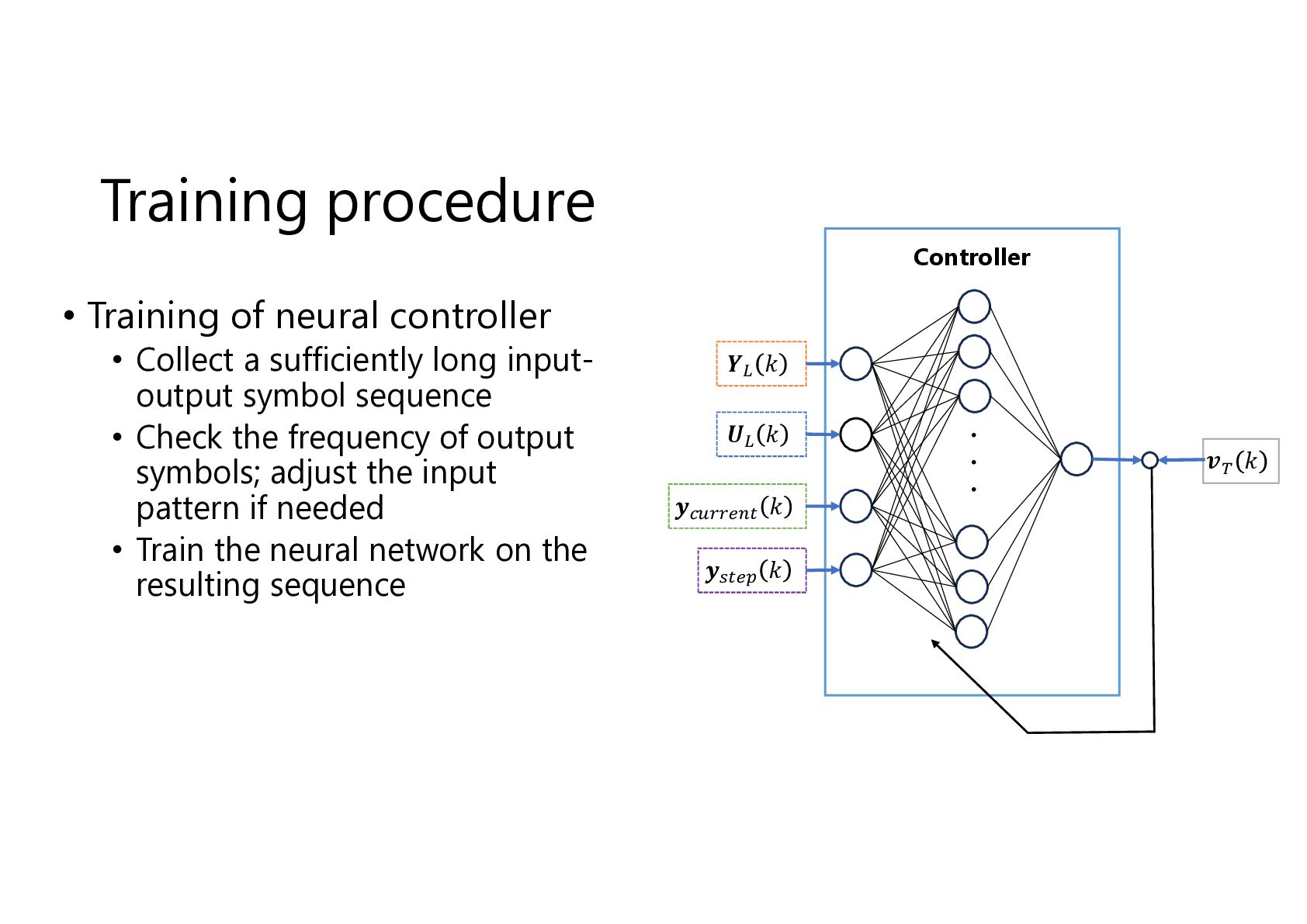
  11. Training procedure Controller • Training of neural controller • Collect

    a sufficiently long inputoutput symbol sequence • Check the frequency of output symbols; adjust the input pattern if needed • Train the neural network on the resulting sequence 𝒀 𝑘 𝑼 𝑘 𝒚 𝑘 𝒚 𝑘 ・ ・ ・ 𝒗 𝑘
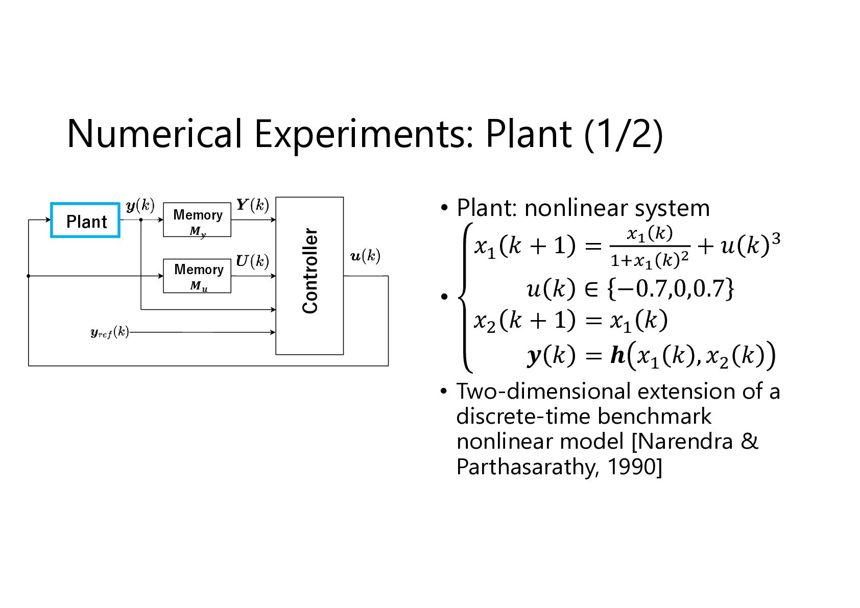
  12. Plant Memory 𝑴𝒚 Memory 𝑴𝒖 Controller Numerical Experiments: Plant (1/2)

    • Plant: nonlinear system 𝑥 𝑘+1 = +𝑢 𝑘 • 𝑢 𝑘 ∈ −0.7,0,0.7 𝑥 𝑘+1 =𝑥 𝑘 𝒚 𝑘 = 𝒉 𝑥 𝑘 ,𝑥 𝑘 • Two-dimensional extension of a discrete-time benchmark nonlinear model [Narendra & Parthasarathy, 1990]
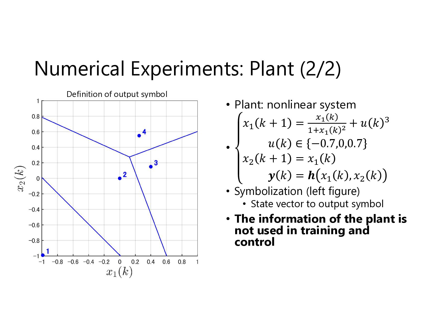
  13. Numerical Experiments: Plant (2/2) Definition of output symbol • Plant:

    nonlinear system 𝑥 𝑘+1 = • +𝑢 𝑘 𝑢 𝑘 ∈ −0.7,0,0.7 𝑥 𝑘+1 =𝑥 𝑘 𝒚 𝑘 = 𝒉 𝑥 𝑘 ,𝑥 𝑘 • Symbolization (left figure) • State vector to output symbol • The information of the plant is not used in training and control
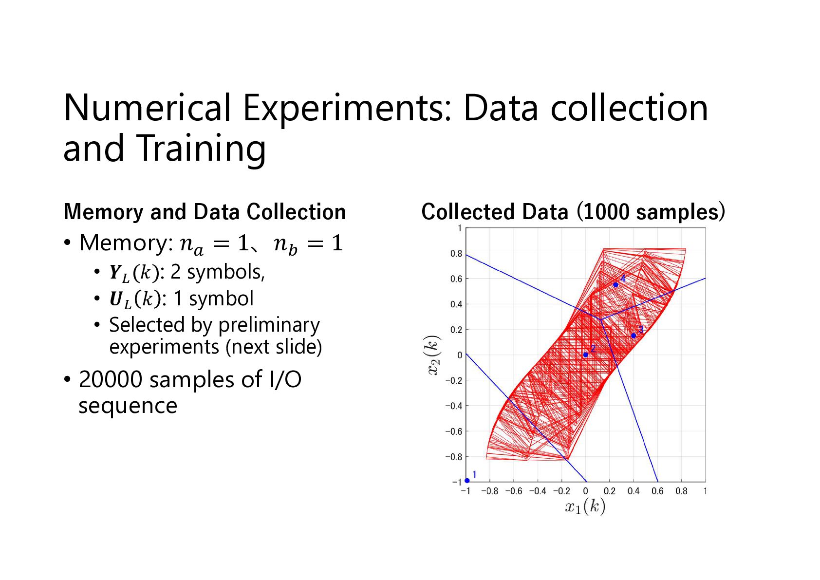
  14. Numerical Experiments: Data collection and Training Memory and Data Collection

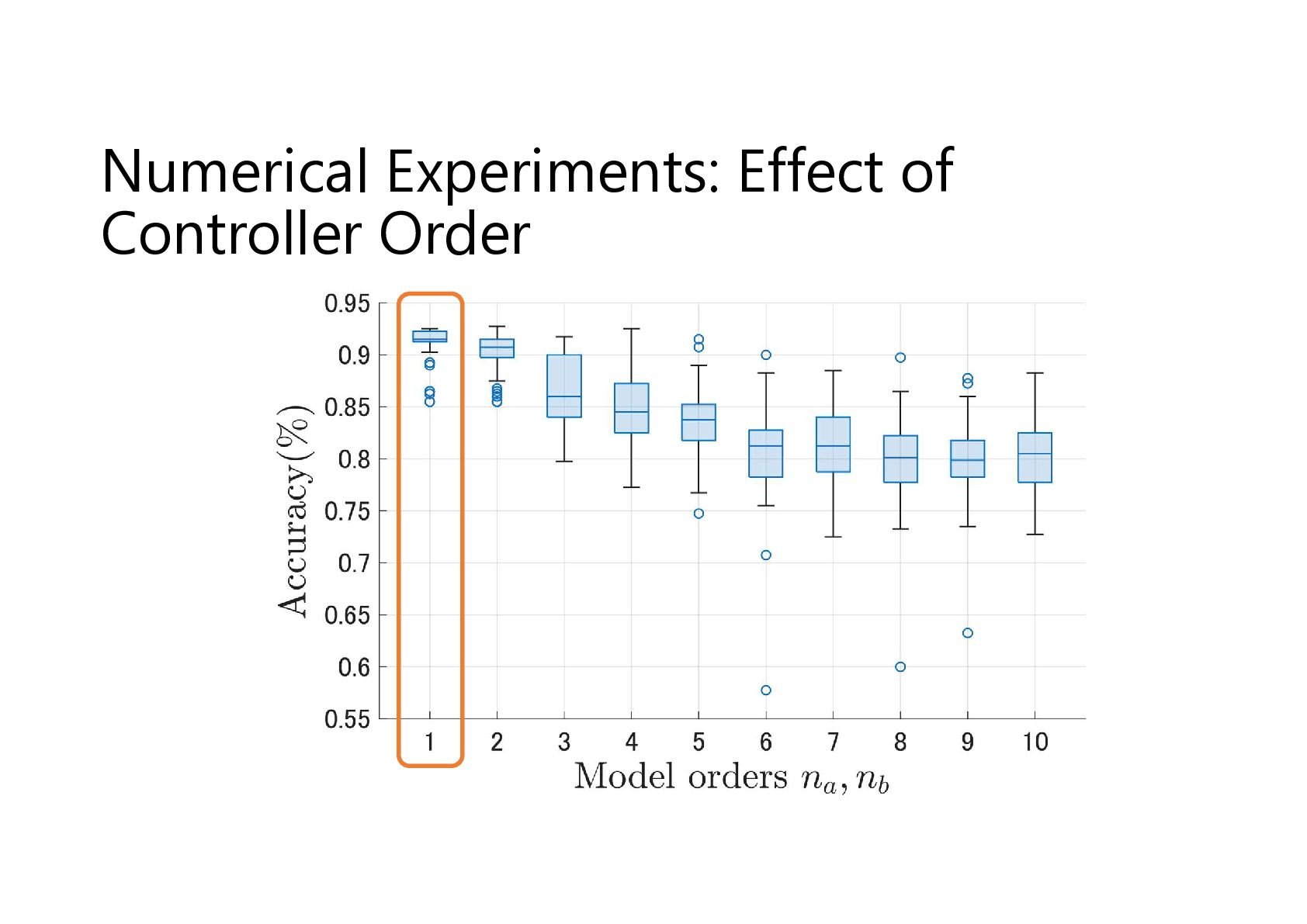
    • Memory: 𝑛 = 1、𝑛 = 1 • 𝒀 (𝑘): 2 symbols, • 𝑼 𝑘 : 1 symbol • Selected by preliminary experiments (next slide) • 20000 samples of I/O sequence Collected Data (1000 samples)
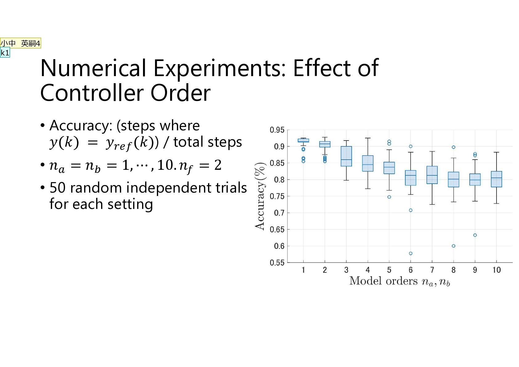
  15. 小中 英嗣4 k1 Numerical Experiments: Effect of Controller Order •

    Accuracy: (steps where 𝑦(𝑘) = 𝑦 (𝑘)) / total steps • 𝑛 = 𝑛 = 1, ⋯ , 10. 𝑛 = 2 • 50 random independent trials for each setting
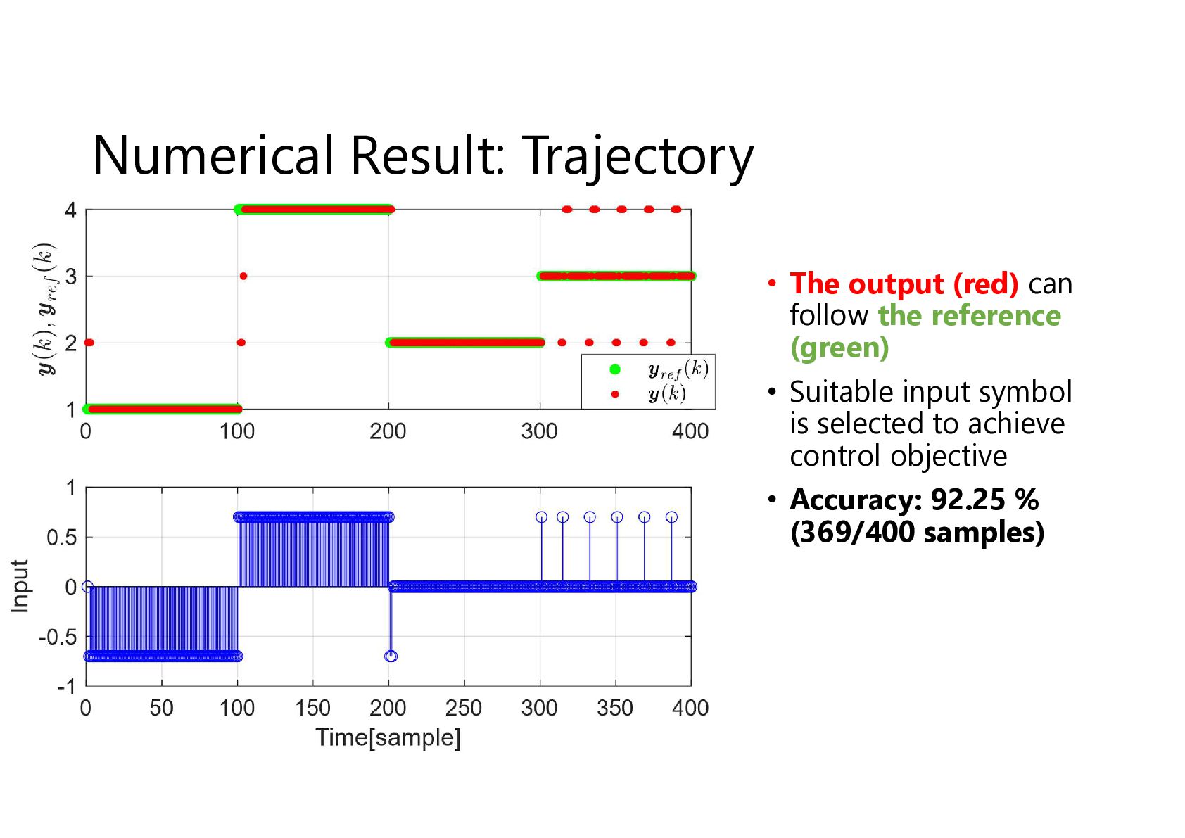
  16. Numerical Result: Trajectory • The output (red) can follow the

    reference (green) • Suitable input symbol is selected to achieve control objective • Accuracy: 92.25 % (369/400 samples)
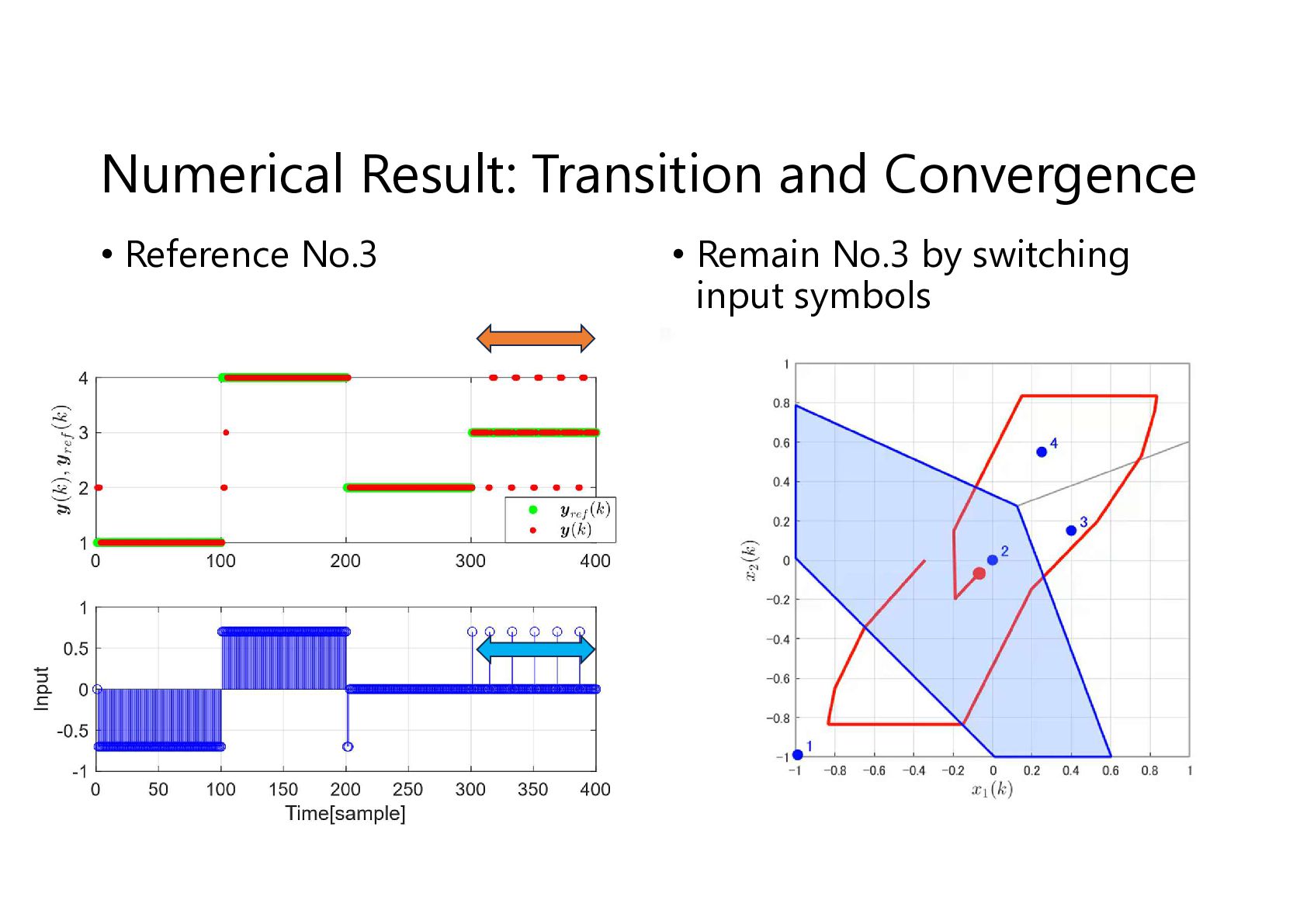
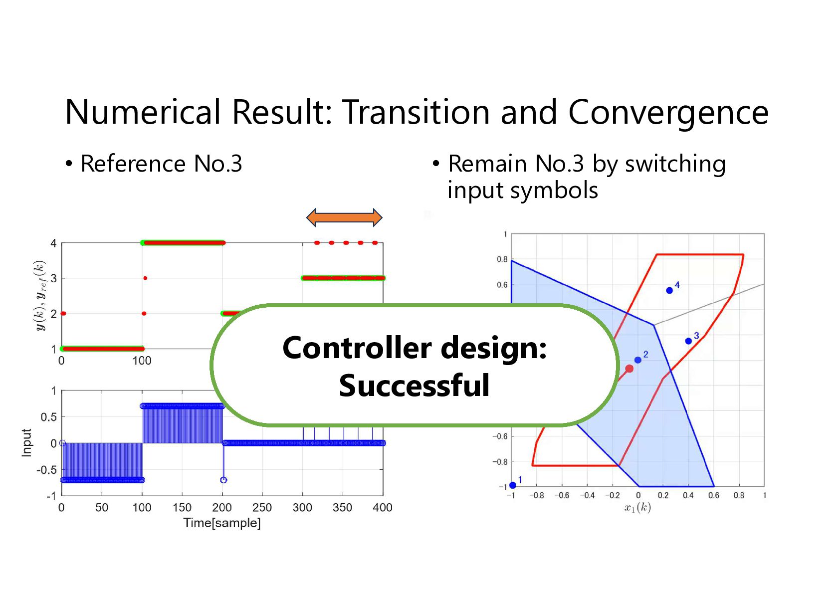
  17. Numerical Result: Transition and Convergence • Reference No.3 • Remain

    No.3 by switching input symbols Controller design: Successful
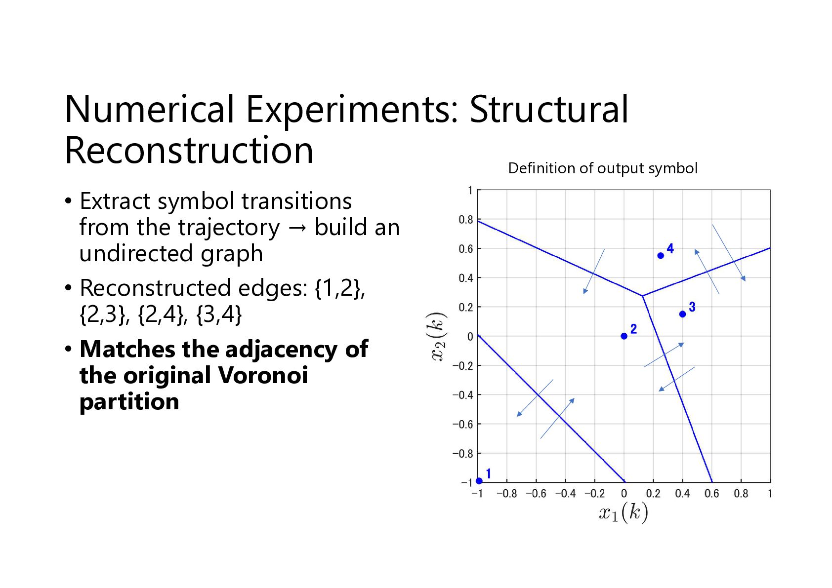
  18. Numerical Experiments: Structural Reconstruction Definition of output symbol • Extract

    symbol transitions from the trajectory → build an undirected graph • Reconstructed edges: {1,2}, {2,3}, {2,4}, {3,4} • Matches the adjacency of the original Voronoi partition
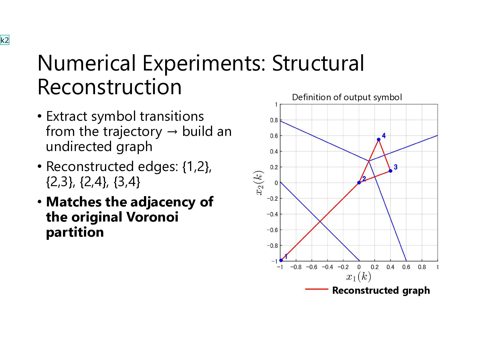
  19. k2 Numerical Experiments: Structural Reconstruction Definition of output symbol •

    Extract symbol transitions from the trajectory → build an undirected graph • Reconstructed edges: {1,2}, {2,3}, {2,4}, {3,4} • Matches the adjacency of the original Voronoi partition Reconstructed graph
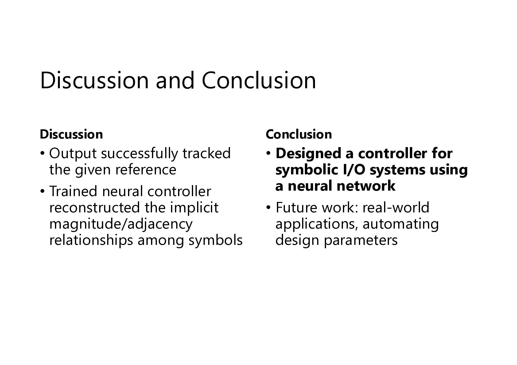
  20. Discussion and Conclusion Discussion Conclusion • Output successfully tracked the

    given reference • Trained neural controller reconstructed the implicit magnitude/adjacency relationships among symbols • Designed a controller for symbolic I/O systems using a neural network • Future work: real-world applications, automating design parameters

More Decks by konakalab

Other Decks in Science