Share
Embed
J601_lec04
5th Year, Integrated Technical Education Cluster AlAmeeria
lec#4, Electronic Principals
Ahmad El-Banna
November 16, 2014
Transcript
39 slides
-
Lecture #4 BJT AC Analysis Instructor: Dr. Ahmad El-Banna November
2014 J-601-1448 Electronic Principals Integrated Technical Education Cluster At AlAmeeria © Ahmad El-Banna -
Agenda 2 J-601-1448 , Lec#4 , Nov 2014 © Ahmad
El-Banna BJT transistor Modeling The re Transistor Model (small signal analysis) Effect of RL and Rs & determining the Current Gain Two-Port Systems Approach Cascaded Systems The Hybrid Equivalent Model (Approximate & Complete ) Troubleshooting and Practical Applications -
BJT TRANSISTOR MODELING 3 J-601-1448 , Lec#4 , Nov 2014
© Ahmad El-Banna -
BJT Transistor Modeling 4 • A model is a combination
of circuit elements, properly chosen, that best approximates the actual behavior of a semiconductor device under specific operating conditions. Ac analysis • Defining the important parameters of any system. J-601-1448 , Lec#4 , Nov 2014 © Ahmad El-Banna -
BJT Transistor Modeling 5 • the ac equivalent of a
transistor network is obtained by: 1. Setting all dc sources to zero and replacing them by a short-circuit equivalent 2. Replacing all capacitors by a short-circuit equivalent 3. Removing all elements bypassed by the short-circuit equivalents introduced by steps 1 and 2 4. Redrawing the network in a more convenient and logical form J-601-1448 , Lec#4 , Nov 2014 © Ahmad El-Banna -
THE r e TRANSISTOR MODEL • Common Emitter Configuration •
Common Base Configuration • Common Collector Configuration • re Model in Different Bias Circuits 6 J-601-1448 , Lec#4 , Nov 2014 © Ahmad El-Banna -
The r e Transistor Model (CE) 7 J-601-1448 , Lec#4
, Nov 2014 © Ahmad El-Banna -
The r e Transistor Model (CB) 8 J-601-1448 , Lec#4
, Nov 2014 © Ahmad El-Banna -
The r e Transistor Model (CC) 9 • For the
common-collector configuration, the model defined for the common-emitter configuration of is normally applied rather than defining a model for the common-collector configuration. • The dc analysis of npn and pnp configurations is quite different in the sense that the currents will have opposite directions and the voltages opposite polarities. • However, for an ac analysis where the signal will progress between positive and negative values, the ac equivalent circuit will be the same. npn versus pnp J-601-1448 , Lec#4 , Nov 2014 © Ahmad El-Banna -
C.E. Fixed Bias Configuration 10 J-601-1448 , Lec#4 , Nov
2014 © Ahmad El-Banna -
Voltage-Divider Bias 11 J-601-1448 , Lec#4 , Nov 2014 ©
Ahmad El-Banna -
EFFECT OF R L AND R S (SYSTEM APPROACH) 12
J-601-1448 , Lec#4 , Nov 2014 © Ahmad El-Banna -
Effect of R L and R s 13 • The
loaded voltage gain of an amplifier is always less than the no-load gain. • The gain obtained with a source resistance in place will always be less than that obtained under loaded or unloaded conditions due to the drop in applied voltage across the source resistance. • For the same configuration AvNL >AvL > Avs . • For a particular design, the larger the level of R L , the greater is the level of ac gain. • For a particular amplifier, the smaller the internal resistance of the signal source, the greater is the overall gain. • For any network that have coupling capacitors, the source and load resistance do not affect the dc biasing levels. J-601-1448 , Lec#4 , Nov 2014 © Ahmad El-Banna -
Effect of R L and R s .. 14 Voltage-divider
ct. J-601-1448 , Lec#4 , Nov 2014 © Ahmad El-Banna -
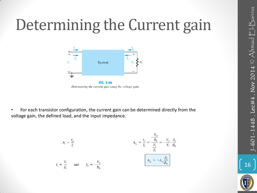
DETERMINING THE CURRENT GAIN 15 J-601-1448 , Lec#4 , Nov
2014 © Ahmad El-Banna -
Determining the Current gain 16 • For each transistor configuration,
the current gain can be determined directly from the voltage gain, the defined load, and the input impedance. J-601-1448 , Lec#4 , Nov 2014 © Ahmad El-Banna -
SUMMARY TABLE 17 J-601-1448 , Lec#4 , Nov 2014 ©
Ahmad El-Banna -
TWO PORT SYSTEMS APPROACH 21 © Ahmad El-Banna J-601-1448 ,
Lec#4 , Nov 2014 -
Cascaded Systems 25 © Ahmad El-Banna • Examples: RC Coupled
ct & Cascode ct • Check Examples: 5.15 & 5.16 J-601-1448 , Lec#4 , Nov 2014 -
THE HYBRID EQUIVALENT MODEL 26 © Ahmad El-Banna J-601-1448 ,
Lec#4 , Nov 2014 -
The Hybrid Equivalent Model 27 © Ahmad El-Banna • The
re model has the advantage that the parameters are defined by the actual operating conditions, • the parameters of the hybrid equivalent circuit are defined in general terms for any operating conditions. short-circuit forward transfer current ratio parameter short-circuit forward transfer current ratio parameter open-circuit reverse transfer voltage ratio parameter short-circuit input-impedance parameter J-601-1448 , Lec#4 , Nov 2014 -
Transistor Hybrid Equivalent ct 28 © Ahmad El-Banna • For
Transistor: J-601-1448 , Lec#4 , Nov 2014 -
Hybrid vs. r e model 29 © Ahmad El-Banna J-601-1448
, Lec#4 , Nov 2014 -
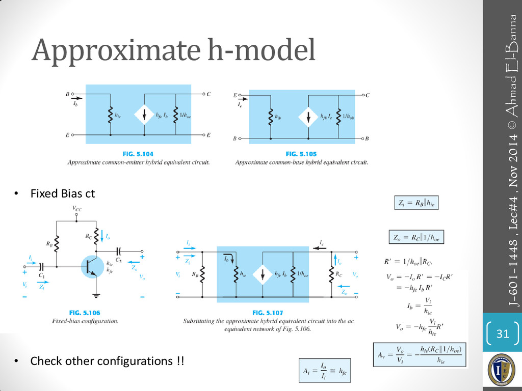
APPROXIMATE & COMPLETE H-MODEL 30 © Ahmad El-Banna J-601-1448 ,
Lec#4 , Nov 2014 -
Approximate h-model 31 © Ahmad El-Banna • Fixed Bias ct
• Check other configurations !! J-601-1448 , Lec#4 , Nov 2014 -
VARIATIONS OF TRANSISTOR PARAMETERS 35 © Ahmad El-Banna J-601-1448 ,
Lec#4 , Nov 2014 -
Troubleshooting 37 © Ahmad El-Banna J-601-1448 , Lec#4 , Nov
2014 In general, therefore, if a system is not working properly, first disconnect the ac source and check the dc biasing levels. -
PRACTICAL APPLICATIONS 38 © Ahmad El-Banna J-601-1448 , Lec#4 ,
Nov 2014 • Audio Mixer • Preamplifier -
• For more details, refer to: • Chapter 5, Electronic
Devices and Circuits, Boylestad. • The lecture is available online at: • https://speakerdeck.com/ahmad_elbanna • For inquires, send to: • [email protected] 39 J-601-1448 , Lec#4 , Nov 2014 © Ahmad El-Banna