[IROS2020] Non-overlapping RGB-D Camera Network Calibration with Monocular Visual Odometry
Non-overlapping RGB-D Camera Network Calibration with Monocular Visual Odometry
Kenji Koide and Emanuele Menegatti
IEEE/RSJ International Conference on Intelligent Robots and Systems (IROS2020)
Koide* and Emanuele Menegatti** * National Institute of Advanced Industrial Science and Technology , Japan ** University of Padova, Italy Code available at: https://github.com/koide3/sparse_dynamic_calibration
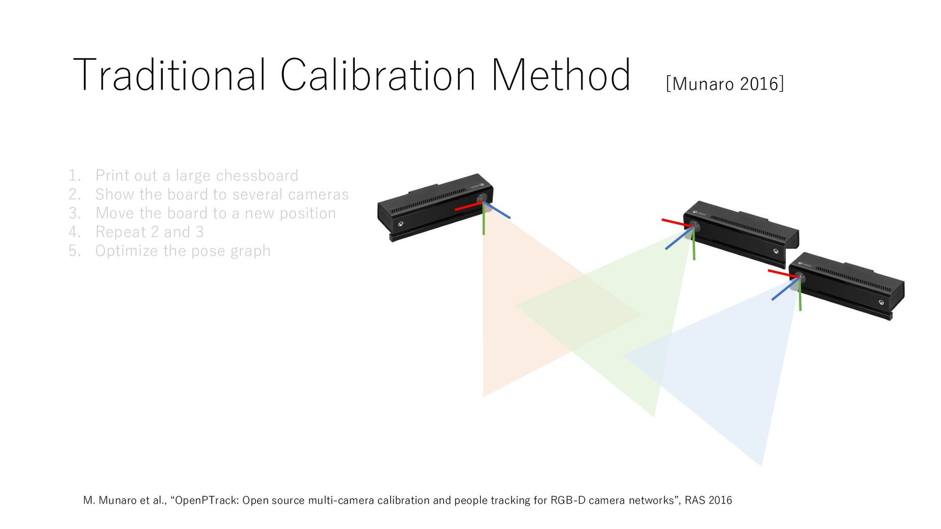
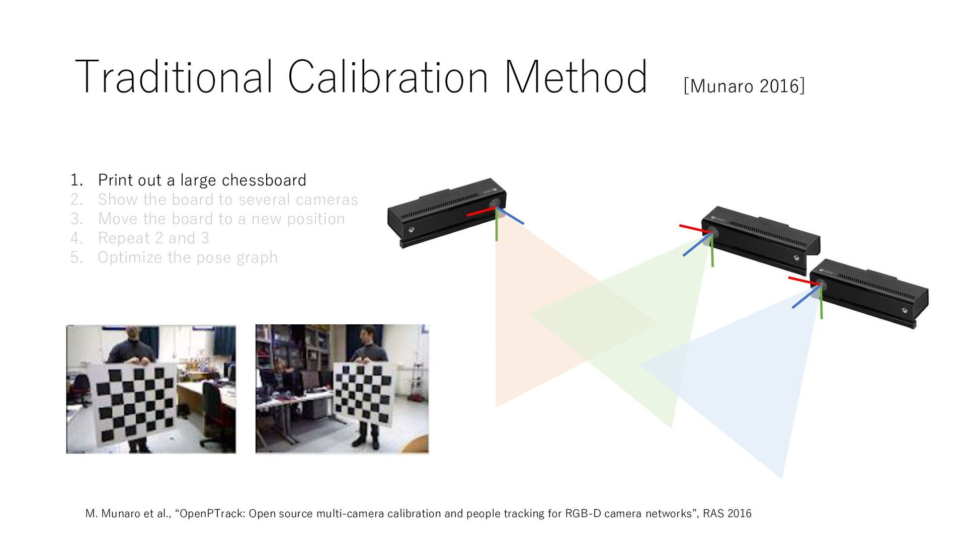
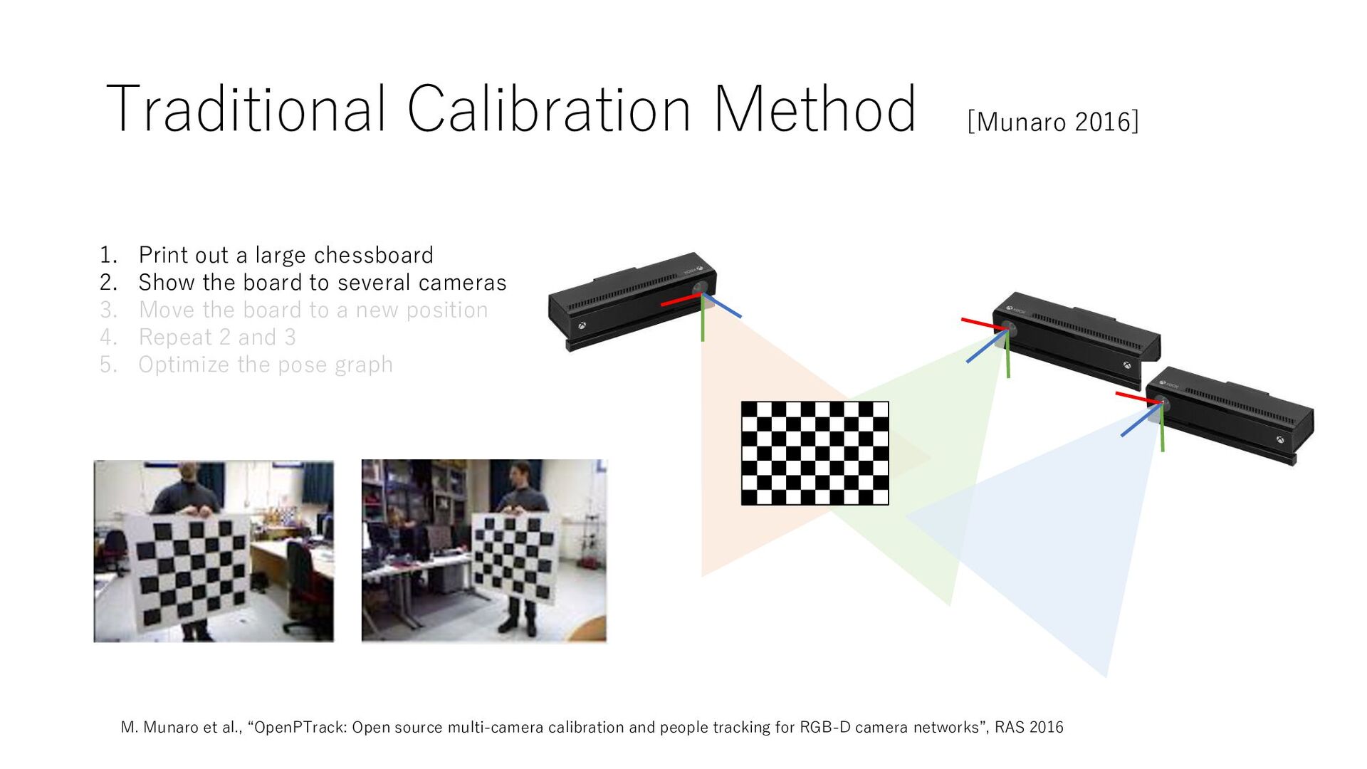
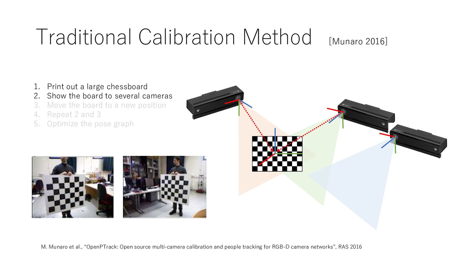
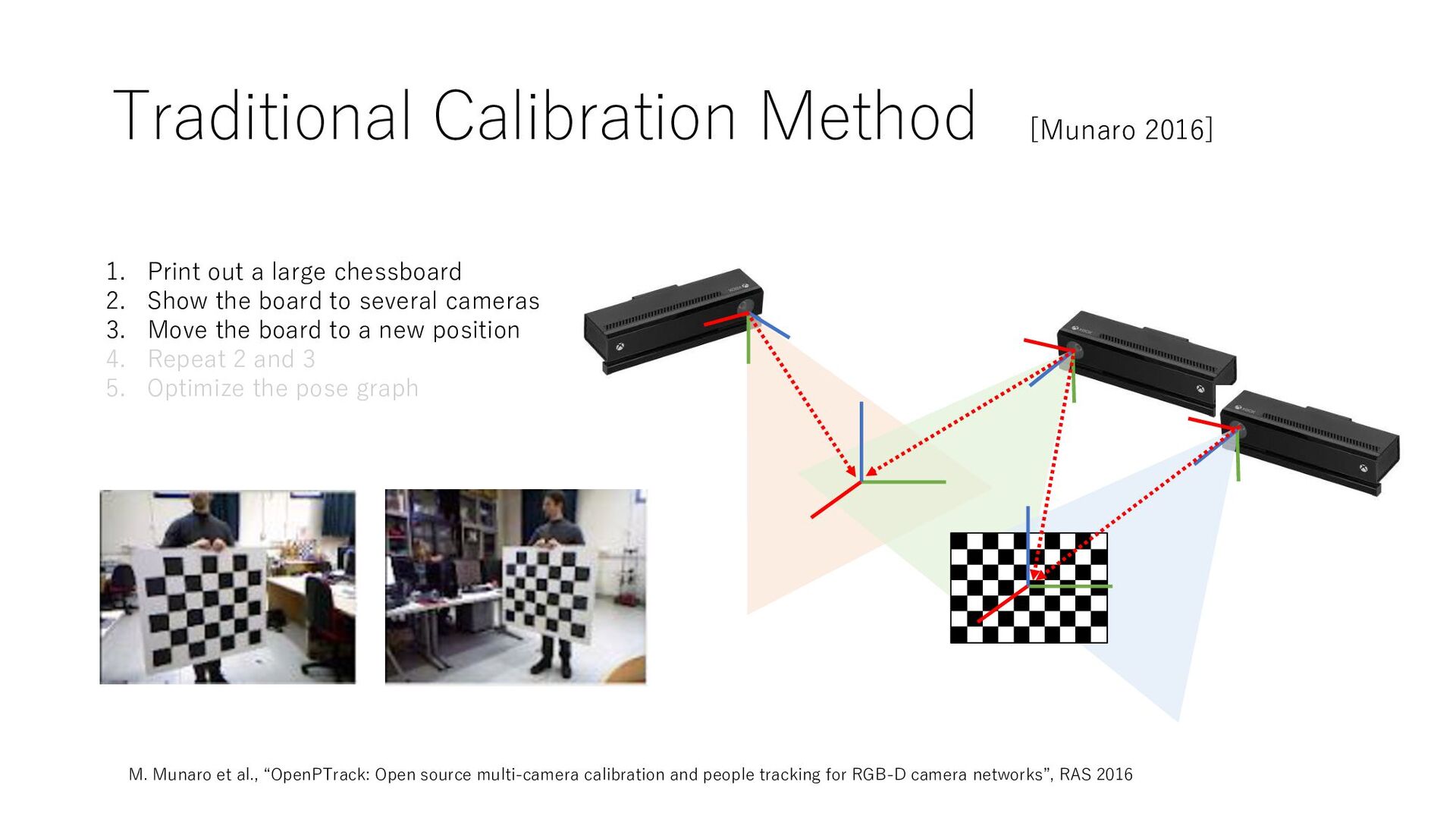
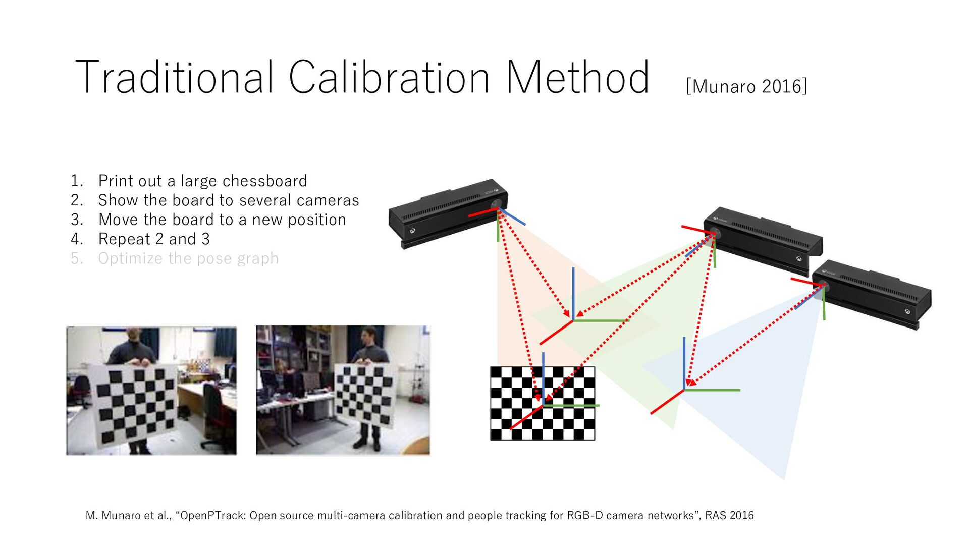
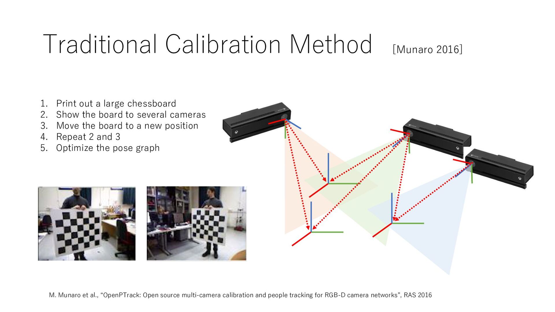
multi-camera calibration and people tracking for RGB-D camera networks”, RAS 2016 [Munaro 2016] 1. Print out a large chessboard 2. Show the board to several cameras 3. Move the board to a new position 4. Repeat 2 and 3 5. Optimize the pose graph
multi-camera calibration and people tracking for RGB-D camera networks”, RAS 2016 [Munaro 2016] 1. Print out a large chessboard 2. Show the board to several cameras 3. Move the board to a new position 4. Repeat 2 and 3 5. Optimize the pose graph
multi-camera calibration and people tracking for RGB-D camera networks”, RAS 2016 [Munaro 2016] 1. Print out a large chessboard 2. Show the board to several cameras 3. Move the board to a new position 4. Repeat 2 and 3 5. Optimize the pose graph
multi-camera calibration and people tracking for RGB-D camera networks”, RAS 2016 [Munaro 2016] 1. Print out a large chessboard 2. Show the board to several cameras 3. Move the board to a new position 4. Repeat 2 and 3 5. Optimize the pose graph
multi-camera calibration and people tracking for RGB-D camera networks”, RAS 2016 [Munaro 2016] 1. Print out a large chessboard 2. Show the board to several cameras 3. Move the board to a new position 4. Repeat 2 and 3 5. Optimize the pose graph
multi-camera calibration and people tracking for RGB-D camera networks”, RAS 2016 [Munaro 2016] 1. Print out a large chessboard 2. Show the board to several cameras 3. Move the board to a new position 4. Repeat 2 and 3 5. Optimize the pose graph
multi-camera calibration and people tracking for RGB-D camera networks”, RAS 2016 [Munaro 2016] 1. Print out a large chessboard 2. Show the board to several cameras 3. Move the board to a new position 4. Repeat 2 and 3 5. Optimize the pose graph
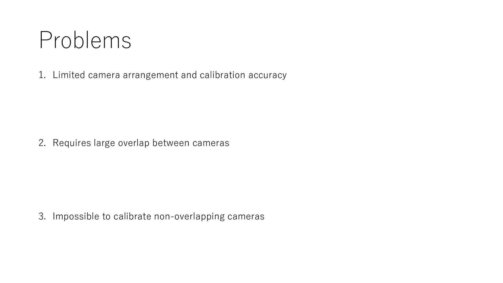
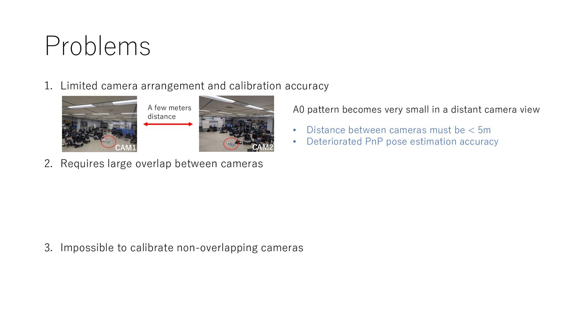
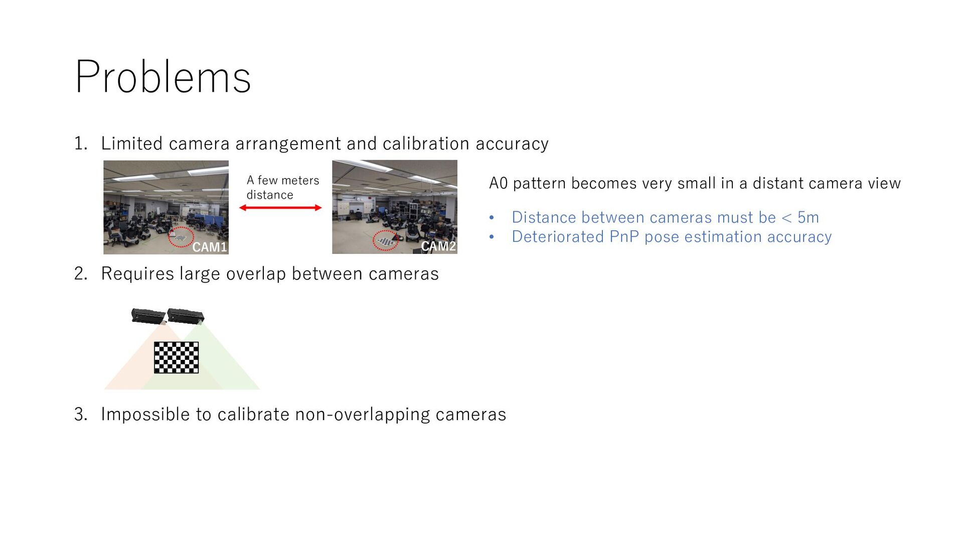
large overlap between cameras 3. Impossible to calibrate non-overlapping cameras A few meters distance CAM1 CAM2 A0 pattern becomes very small in a distant camera view • Distance between cameras must be < 5m • Deteriorated PnP pose estimation accuracy
large overlap between cameras 3. Impossible to calibrate non-overlapping cameras A few meters distance CAM1 CAM2 A0 pattern becomes very small in a distant camera view • Distance between cameras must be < 5m • Deteriorated PnP pose estimation accuracy
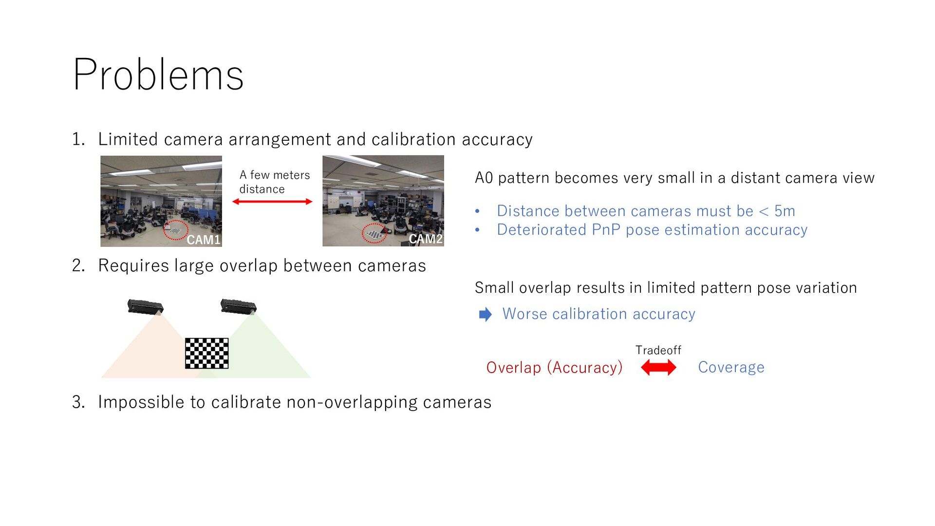
large overlap between cameras 3. Impossible to calibrate non-overlapping cameras A few meters distance CAM1 CAM2 A0 pattern becomes very small in a distant camera view • Distance between cameras must be < 5m • Deteriorated PnP pose estimation accuracy Overlap (Accuracy) Coverage Tradeoff Small overlap results in limited pattern pose variation Worse calibration accuracy
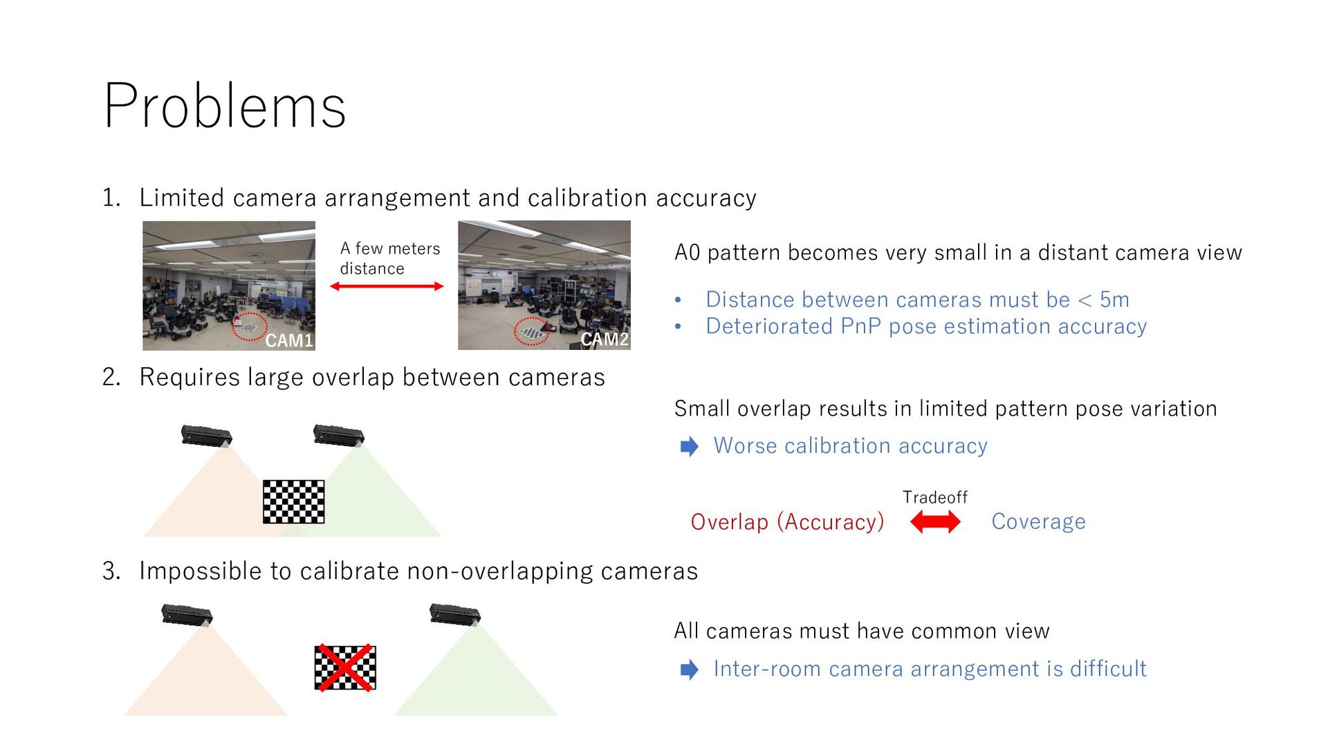
large overlap between cameras 3. Impossible to calibrate non-overlapping cameras A few meters distance CAM1 CAM2 A0 pattern becomes very small in a distant camera view • Distance between cameras must be < 5m • Deteriorated PnP pose estimation accuracy Overlap (Accuracy) Coverage Tradeoff Small overlap results in limited pattern pose variation Worse calibration accuracy All cameras must have common view Inter-room camera arrangement is difficult
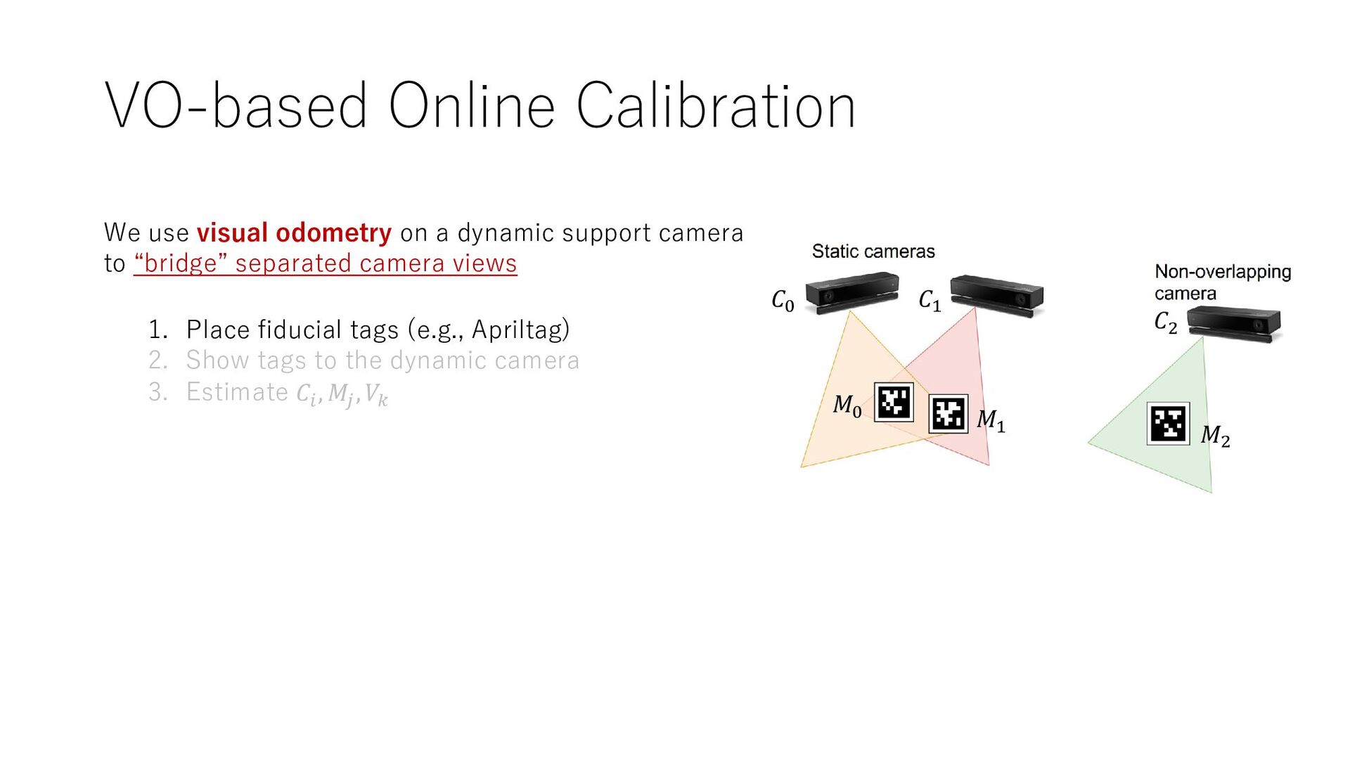
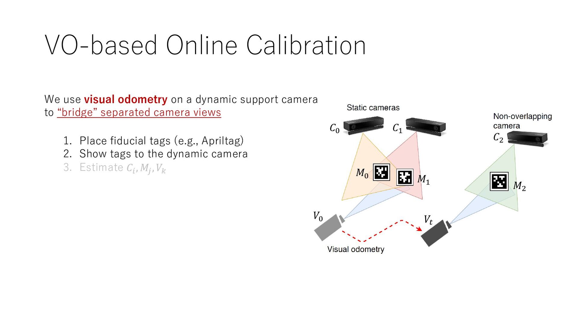
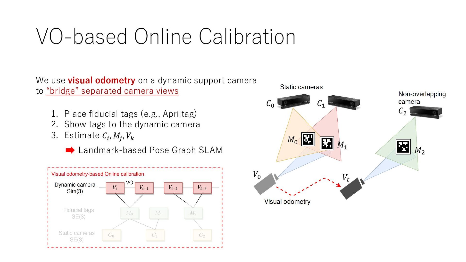
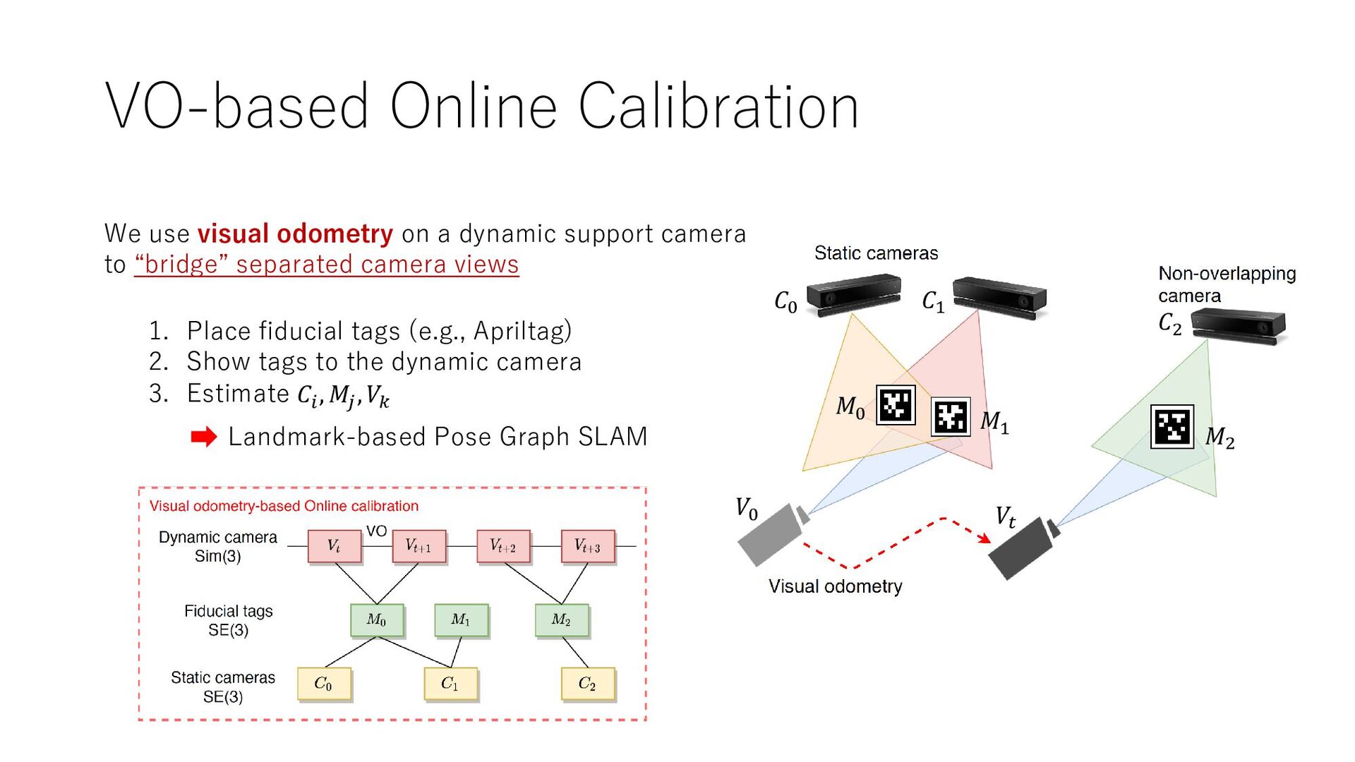
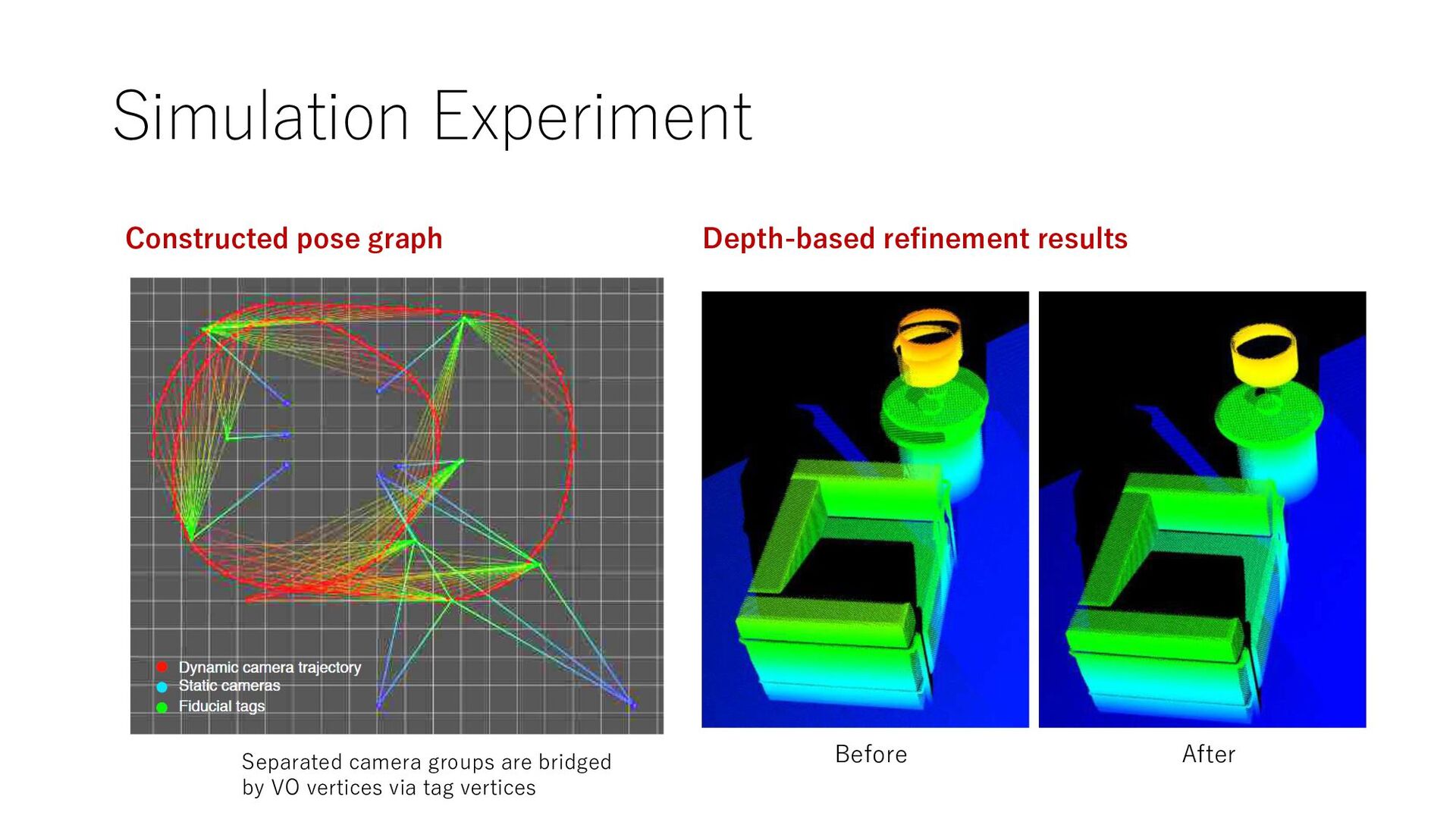
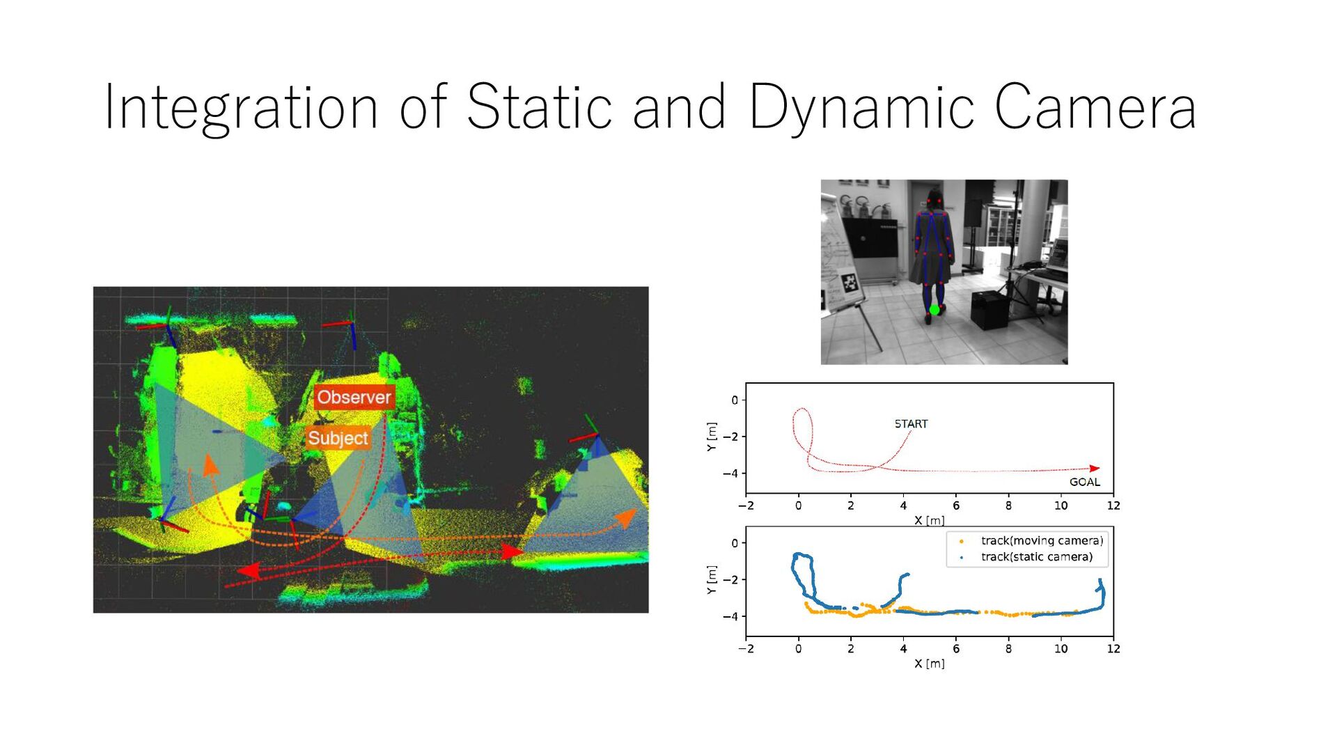
support camera to “bridge” separated camera views 𝐶0 𝐶1 𝐶2 𝑀0 𝑀1 𝑀2 1. Place fiducial tags (e.g., Apriltag) 2. Show tags to the dynamic camera 3. Estimate 𝐶𝑖 , 𝑀𝑗 , 𝑉𝑘
support camera to “bridge” separated camera views 𝐶0 𝐶1 𝐶2 𝑀0 𝑀1 𝑀2 𝑉0 𝑉𝑡 1. Place fiducial tags (e.g., Apriltag) 2. Show tags to the dynamic camera 3. Estimate 𝐶𝑖 , 𝑀𝑗 , 𝑉𝑘
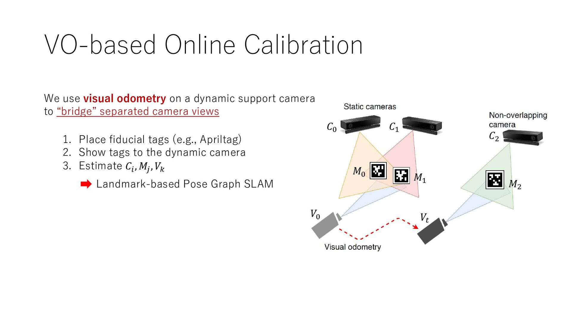
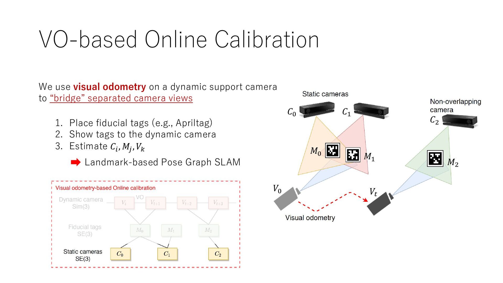
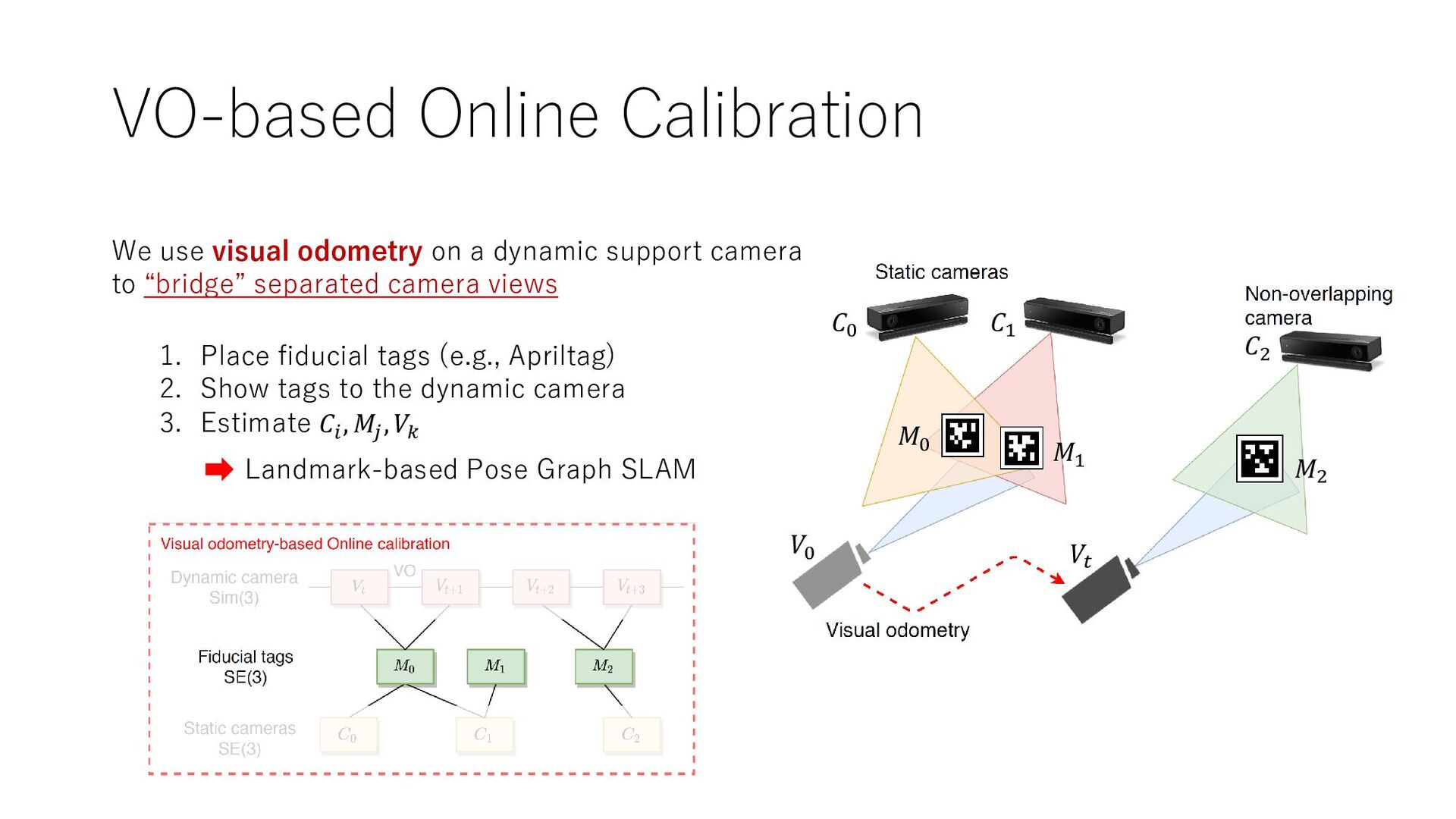
support camera to “bridge” separated camera views 𝐶0 𝐶1 𝐶2 𝑀0 𝑀1 𝑀2 𝑉0 𝑉𝑡 1. Place fiducial tags (e.g., Apriltag) 2. Show tags to the dynamic camera 3. Estimate 𝐶𝑖 , 𝑀𝑗 , 𝑉𝑘 Landmark-based Pose Graph SLAM
support camera to “bridge” separated camera views 𝐶0 𝐶1 𝐶2 𝑀0 𝑀1 𝑀2 𝑉0 𝑉𝑡 1. Place fiducial tags (e.g., Apriltag) 2. Show tags to the dynamic camera 3. Estimate 𝐶𝑖 , 𝑀𝑗 , 𝑉𝑘 Landmark-based Pose Graph SLAM
support camera to “bridge” separated camera views 𝐶0 𝐶1 𝐶2 𝑀0 𝑀1 𝑀2 𝑉0 𝑉𝑡 1. Place fiducial tags (e.g., Apriltag) 2. Show tags to the dynamic camera 3. Estimate 𝐶𝑖 , 𝑀𝑗 , 𝑉𝑘 Landmark-based Pose Graph SLAM
support camera to “bridge” separated camera views 𝐶0 𝐶1 𝐶2 𝑀0 𝑀1 𝑀2 𝑉0 𝑉𝑡 1. Place fiducial tags (e.g., Apriltag) 2. Show tags to the dynamic camera 3. Estimate 𝐶𝑖 , 𝑀𝑗 , 𝑉𝑘 Landmark-based Pose Graph SLAM
support camera to “bridge” separated camera views 𝐶0 𝐶1 𝐶2 𝑀0 𝑀1 𝑀2 𝑉0 𝑉𝑡 1. Place fiducial tags (e.g., Apriltag) 2. Show tags to the dynamic camera 3. Estimate 𝐶𝑖 , 𝑀𝑗 , 𝑉𝑘 Landmark-based Pose Graph SLAM
support camera to “bridge” separated camera views 1. Place fiducial tags (e.g., Apriltag) 2. Show tags to the dynamic camera 3. Estimate 𝐶𝑖 , 𝑀𝑗 , 𝑉𝑘 𝐶0 𝐶1 𝐶2 𝑀0 𝑀1 𝑀2 𝑉0 𝑉𝑡 Landmark-based Pose Graph SLAM
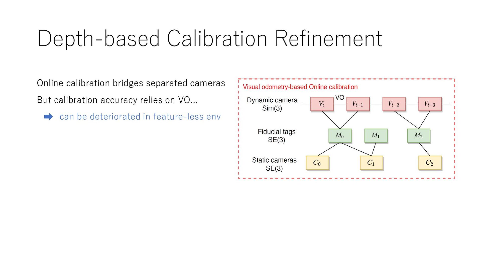
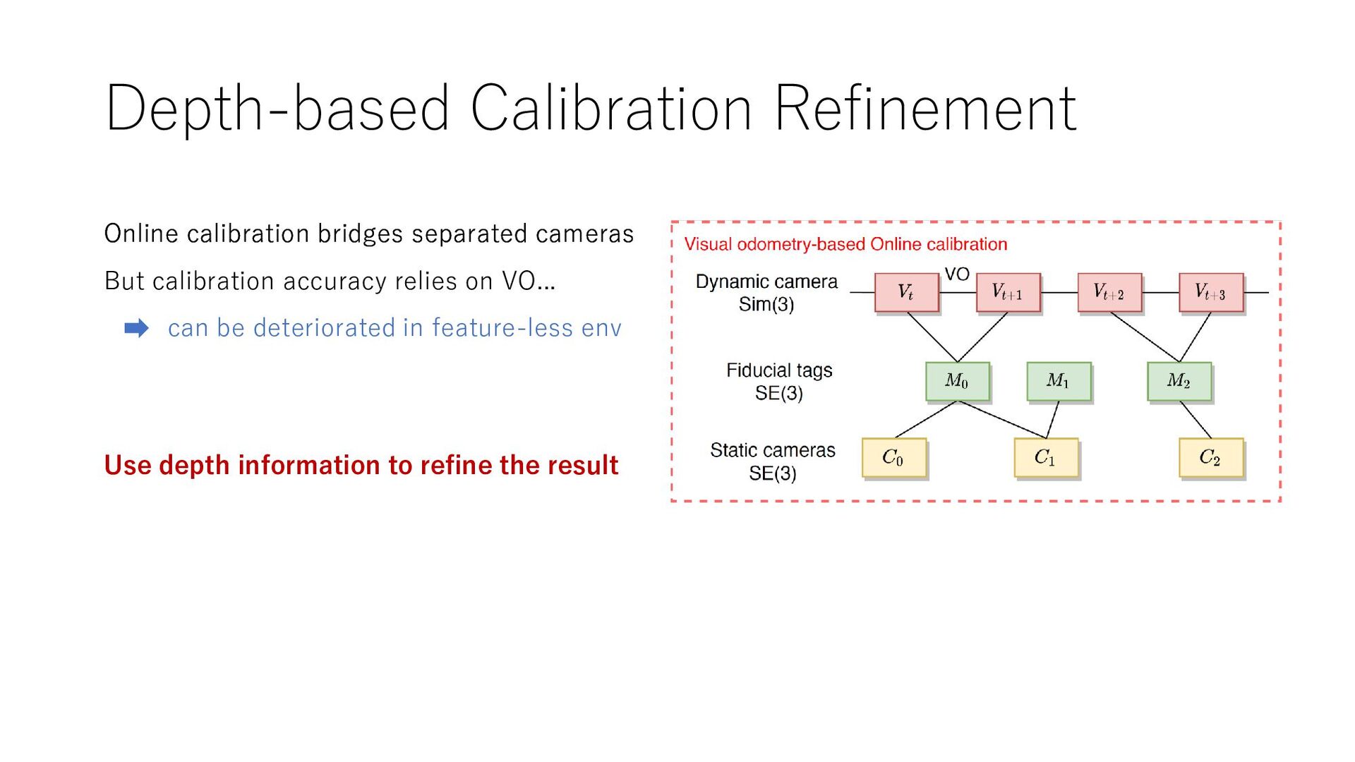
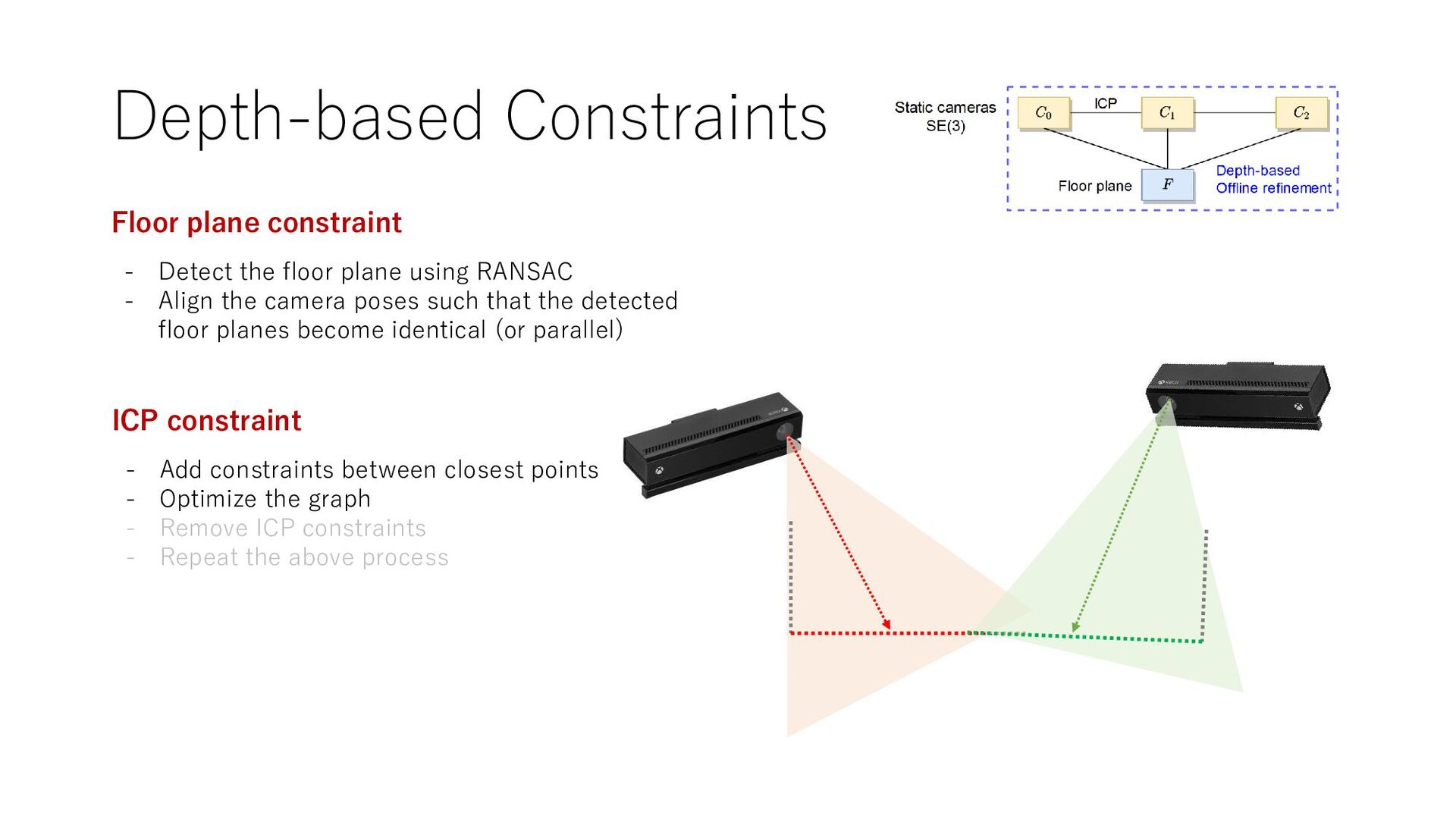
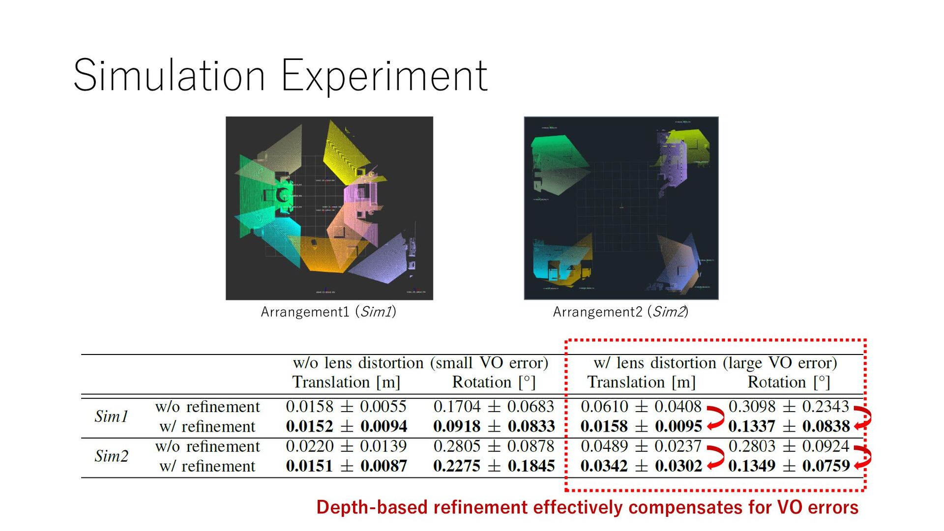
accuracy relies on VO... can be deteriorated in feature-less env Online calibration bridges separated cameras Use depth information to refine the result
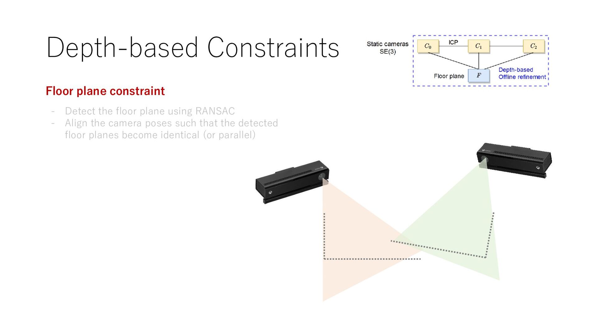
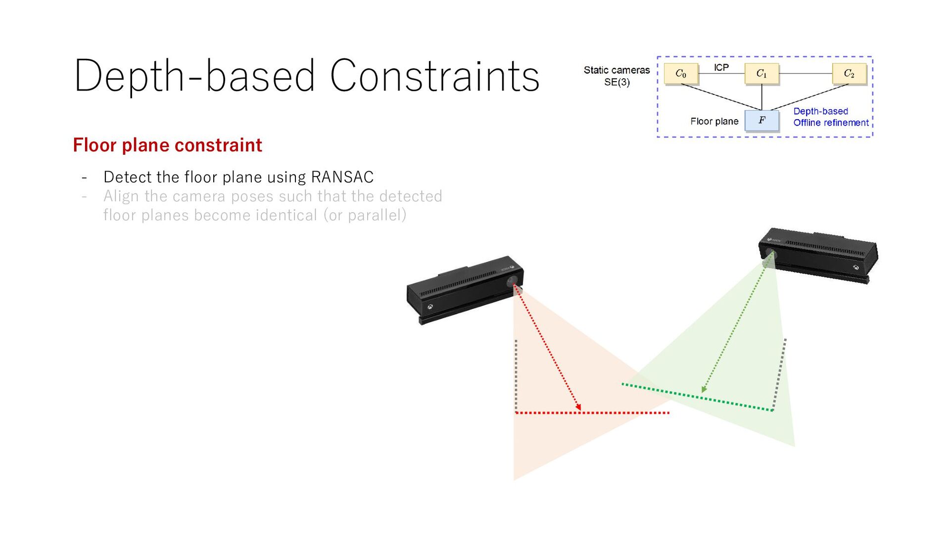
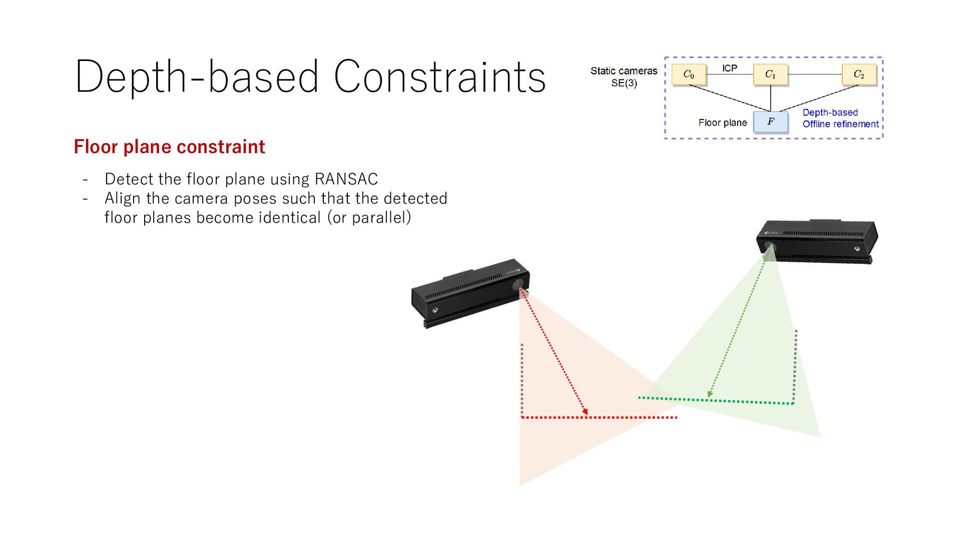
accuracy relies on VO... can be deteriorated in feature-less env Online calibration bridges separated cameras • Floor plane constraint • ICP constraint Use depth information to refine the result
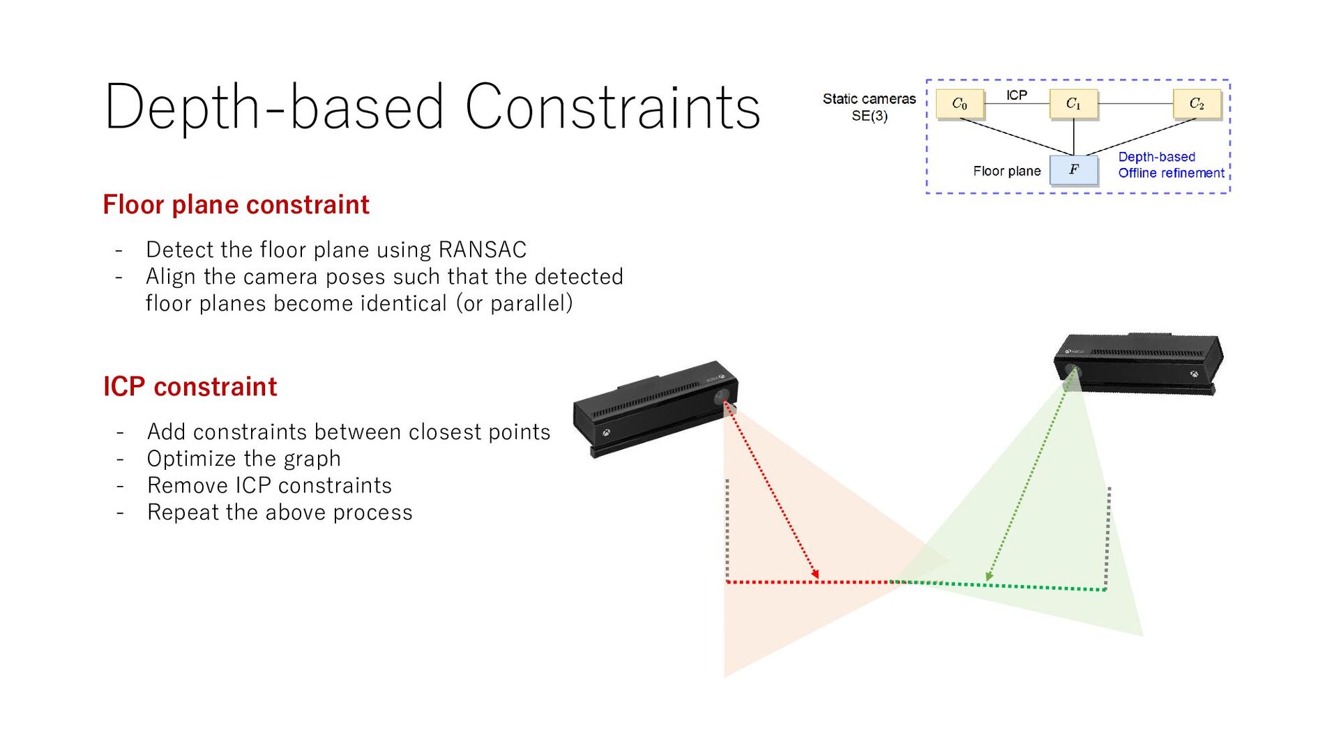
using RANSAC - Align the camera poses such that the detected floor planes become identical (or parallel) ICP constraint - Add constraints between closest points - Optimize the graph - Remove ICP constraints - Repeat the above process
using RANSAC - Align the camera poses such that the detected floor planes become identical (or parallel) ICP constraint - Add constraints between closest points - Optimize the graph - Remove ICP constraints - Repeat the above process
using RANSAC - Align the camera poses such that the detected floor planes become identical (or parallel) ICP constraint - Add constraints between closest points - Optimize the graph - Remove ICP constraints - Repeat the above process
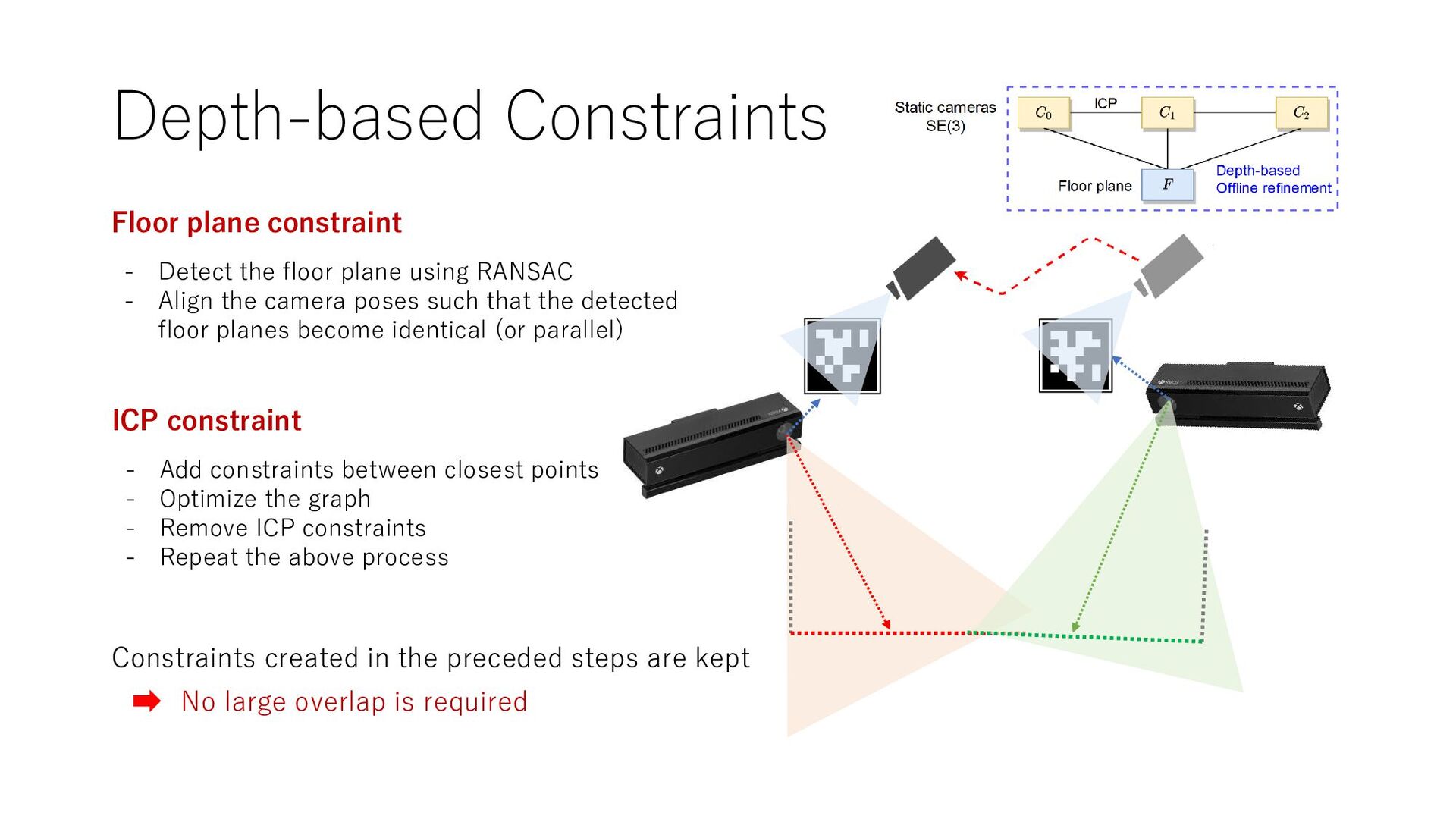
using RANSAC - Align the camera poses such that the detected floor planes become identical (or parallel) ICP constraint - Add constraints between closest points - Optimize the graph - Remove ICP constraints - Repeat the above process Constraints created in the preceded steps are kept No large overlap is required
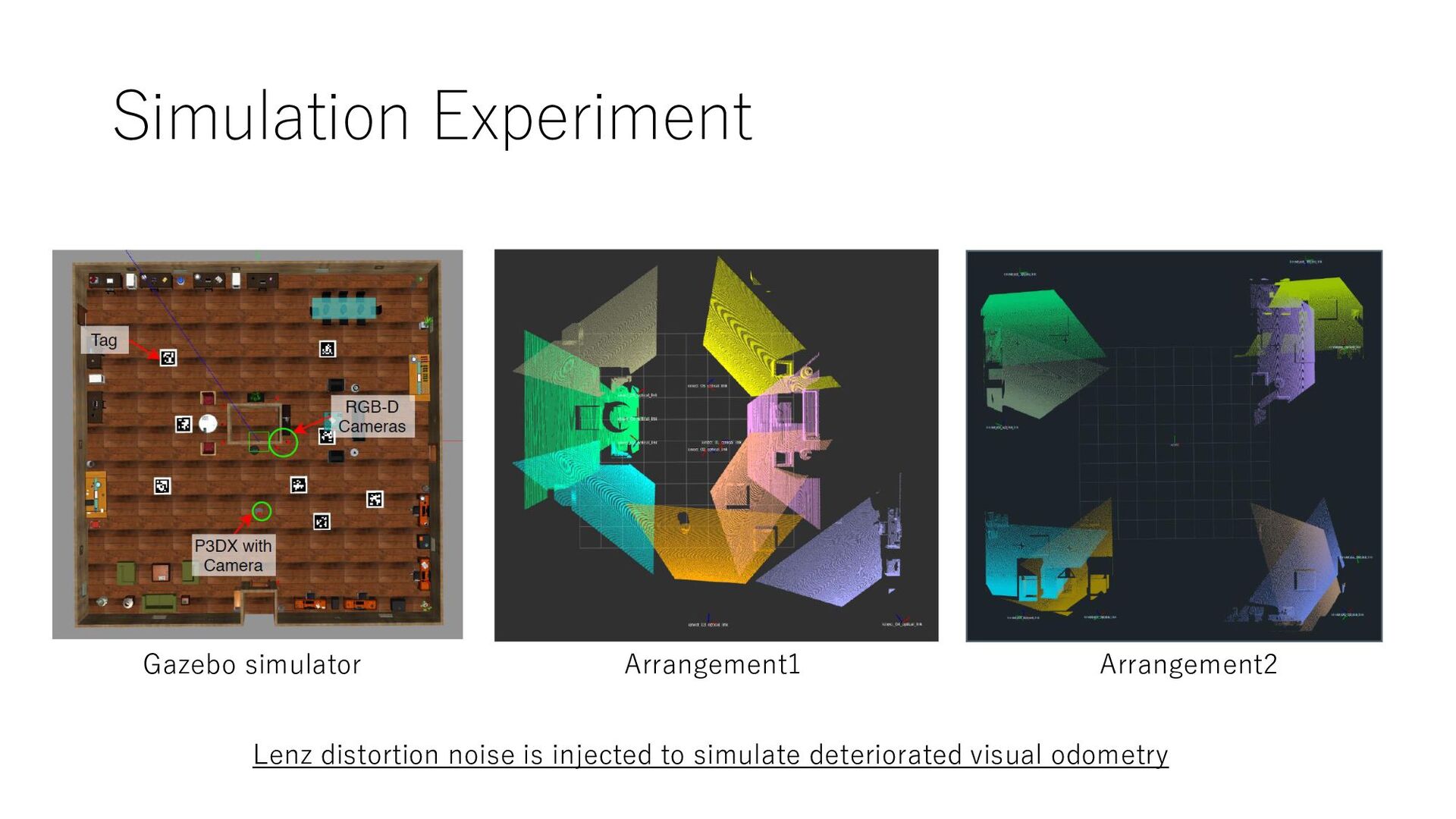
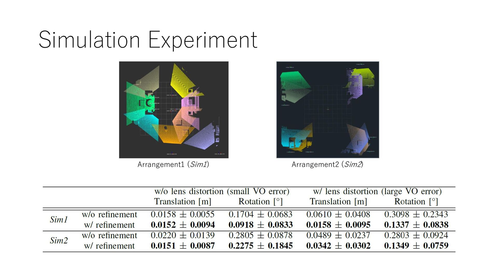
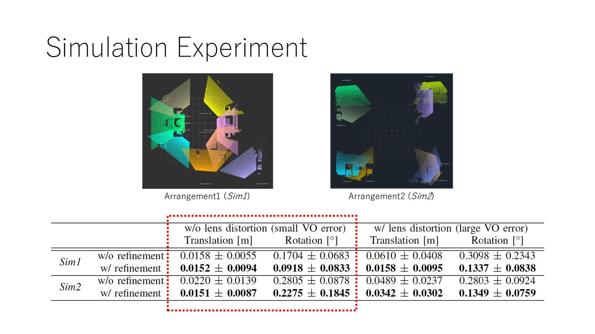
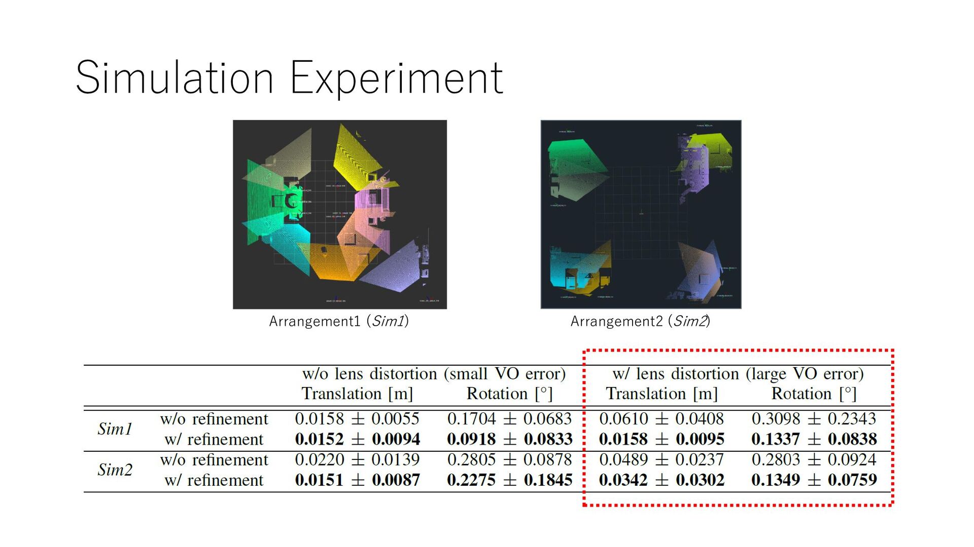
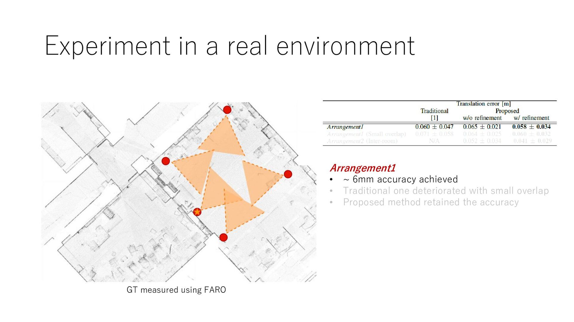
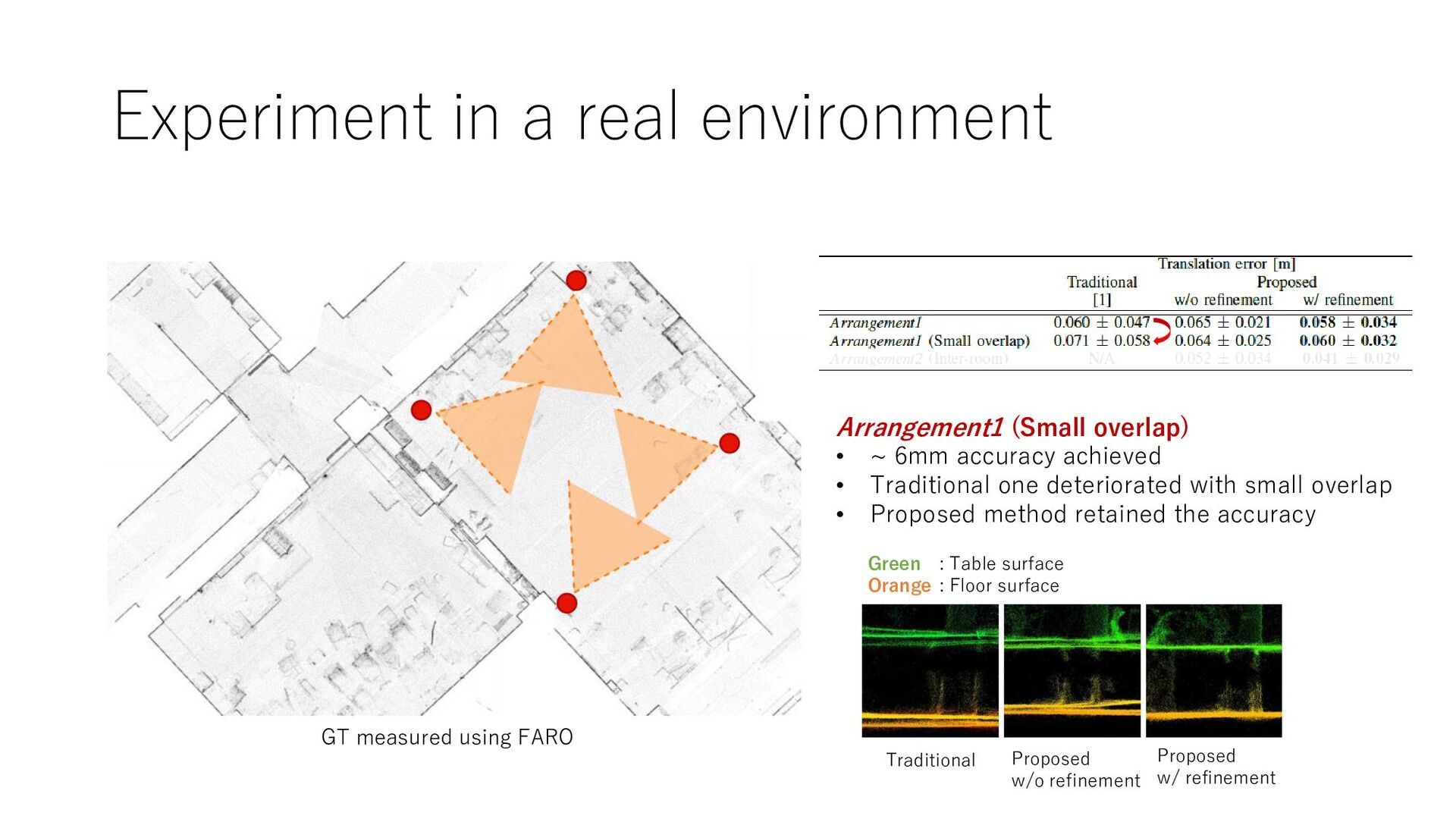
6mm accuracy achieved • Traditional one deteriorated with small overlap • Proposed method retained the accuracy GT measured using FARO Traditional Proposed w/o refinement Proposed w/ refinement Green Orange : Table surface : Floor surface
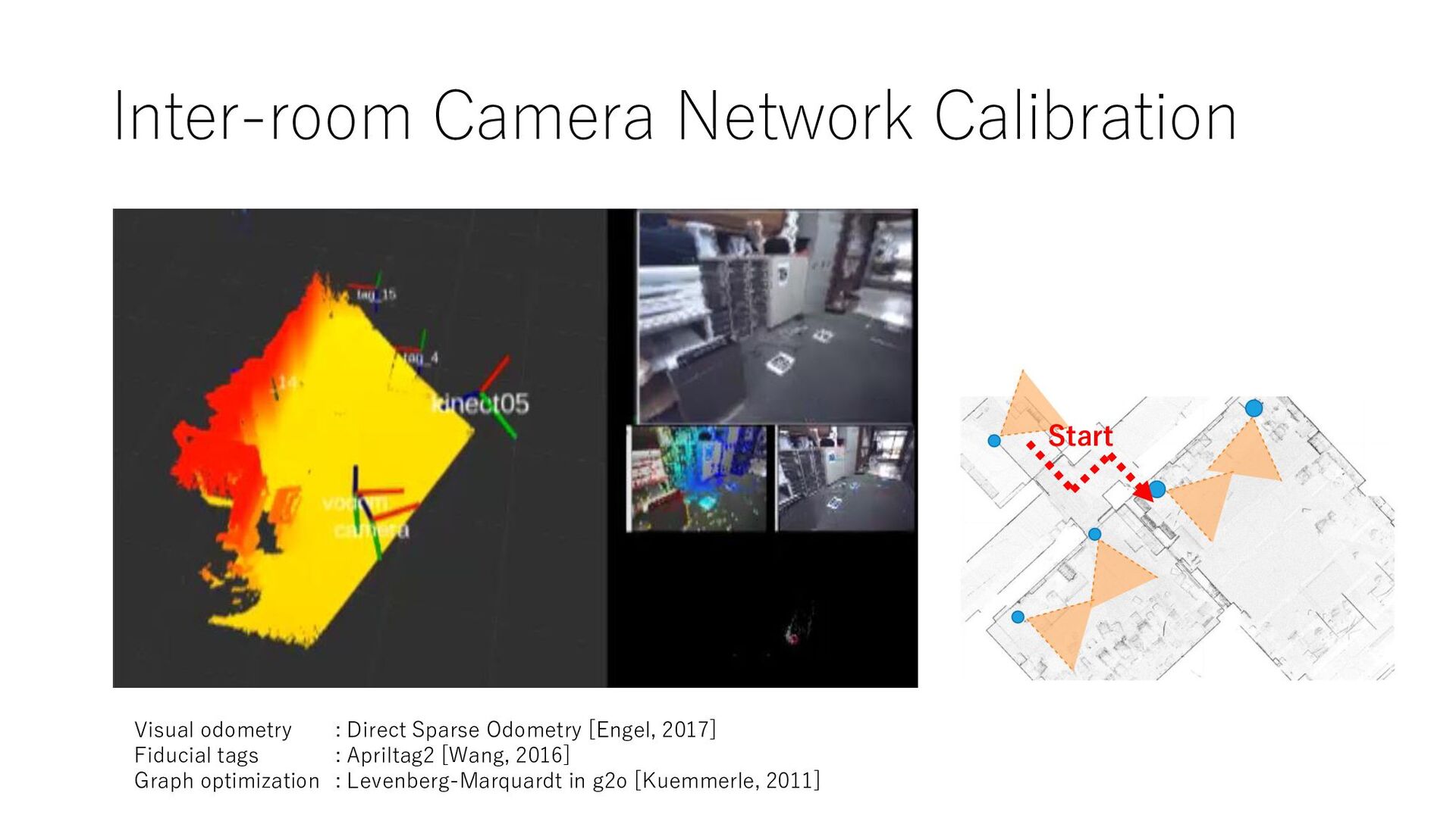
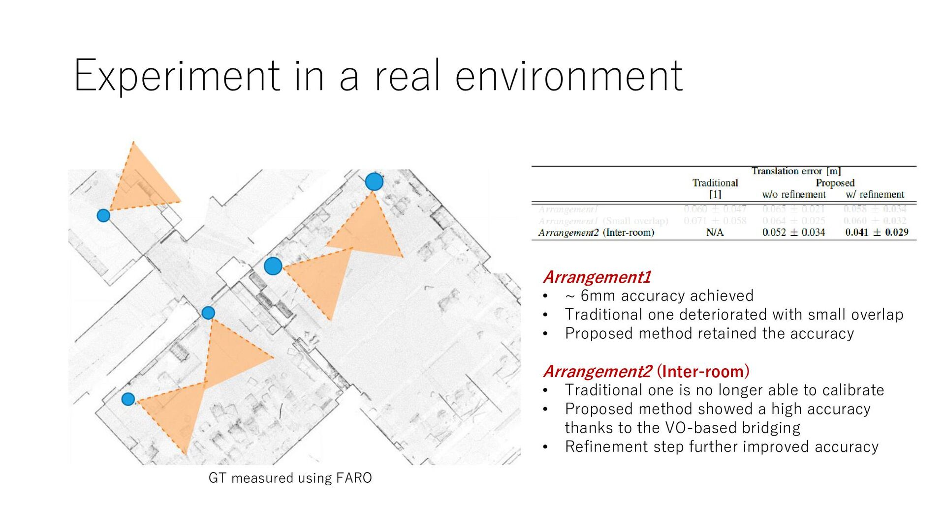
achieved • Traditional one deteriorated with small overlap • Proposed method retained the accuracy Arrangement2 (Inter-room) • Traditional one is no longer able to calibrate • Proposed method showed a high accuracy thanks to the VO-based bridging • Refinement step further improved accuracy GT measured using FARO
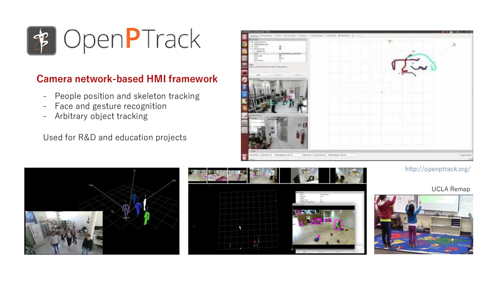
![Camera Network [Cho 2017] [Karasev, 2017] [Byeon, 2015] • Surveillance](https://files.speakerdeck.com/presentations/3b84e12c319b4d26be5cb18cae85dc92/slide_1.jpg)